What Substrate Material Best Fits Your High-Speed Circuits?
This file type includes high-resolution graphics and schematics when applicable.
Printed-circuit-board (PCB) materials contain the transmission lines and components that enable discrete RF/microwave circuits. They consist of numerous materials, including plastics, epoxy, glass, and ceramics, in rigid and flexible forms and with qualities that serve many different circuit designs. Understanding how PCB material parameters relate to circuit performance can simplify the task of matching a PCB material to an application as well as to a circuit fabrication process.
Quite simply, PCB materials are insulators; they provide electrical isolation between transmission lines, components, and semiconductor devices mounted upon them. Should a PCB material’s dielectric properties break down, such as from excessive power or voltage, the isolation will diminish and the material will begin to conduct electricity, to the detriment of the attached components.
Determining Dielectric Constant
PCB materials are commercially available in many formulations at numerous performance levels, with the most usual tradeoff being between price and performance. A large number of parameters describe a circuit material’s performance, with dielectric constant (εr or Dk) probably the most popular starting point when comparing materials.
The Dk or relative permittivity of a circuit material is a measure of the capacitance or charge stored between two conductors on a dielectric material, compared to the same two conductors in a vacuum. Higher Dk values relate to higher flux densities, with the dimensions of microwave transmission lines (e.g., microstrip) diminishing with increasing values of Dk for a particular frequency.
For a given frequency and characteristic impedance, conductors are wider for materials with lower Dk values, yielding less loss. The circuits on lower-Dk materials will have larger dimensions, but this may also mean higher yields for a particular circuit manufacturing process—all tradeoffs to consider when choosing a PCB material.
The dielectric constant of a vacuum, at 1.0, serves as the reference for other dielectric materials, such as Teflon with a dielectric constant of 2.1. Lower-Dk materials like Teflon or polytetrafluroethylene (PTFE) have often been used in RF/microwave circuits. However, the range of Dk values for high-frequency circuit materials is quite wide, from below 2.1 to above 10.0, for miniaturizing lower-frequency circuits with longer wavelengths.
The dielectric constant of PCB materials will vary with humidity and temperature. Since water has a high Dk value of about 80, any material that absorbs water in a high-humidity environment will exhibit an increase in Dk, resulting in a change in high-frequency circuit performance. Changes in ambient temperature or from heat generated by high-power circuit components can also affect Dk, characterized by a parameter known as thermal coefficient of Dk (TCDk). For stable circuit performance, lower values are preferred, over the widest operating-temperature ranges possible.
Another important material parameter related to temperature is coefficient of thermal expansion (CTE), a measure of how a material changes mechanically with temperature. Such changes are unavoidable, but ideally should be as close in value to other materials, such as copper conductors, integrated with the PCB material to minimize temperature-related stress. In automotive electronic applications, for example, where operating temperatures can cover a wide range, consideration should be given to both TCDk and CTE.
PCB materials can be specified in many sizes, thicknesses, and dielectric constants. Materials suppliers may characterize their materials in terms of dielectric constant in the z-axis (thickness of the material) and/or in the x-y plane (length and width of the material), and typically at a particular test frequency, such as 1 or 10 GHz. For circuit designs requiring channels that are closely matched in phase and/or amplitude, or otherwise require tight performance tolerances, PCB materials can also be specified with varying degrees of εr tolerance across a circuit board. This helps minimize the performance variations in the transmission lines and other circuit structures fabricated on those circuit boards.
Dissipation factor (Df) or loss tangent serves as a means of comparing loss characteristics for different PCB material. It is usually determined through the thickness or z-axis of the material, and at different frequencies and ambient temperatures. Dissipation factor is a function of frequency and rises with increasing frequency; lower values represent lower loss characteristics.
Certain types of general-purpose circuit materials, such as flame-retardant FR-4 glass-reinforced epoxy laminate or G-10 glass/epoxy composite materials, have long served a variety of analog and digital circuit applications. That’s because they have simple processing requirements compared to softer materials such as PTFE. Drilling and plating holes with metal conductors, as required for plated throughholes (PTHs) in multilayer circuits, can be more complex (and costly) in such softer materials. Thus, manufacturing ease is another factor to consider when selecting a circuit material.
Handling the Heat
Above certain power levels, heat will generate and higher temperatures will occur at thermal mismatch points or at junctions, such as where a packaged component is mounted on a PCB. A PCB must be able to efficiently dissipate heat to avoid thermal stress on the material and its transmission lines and components.
Circuit materials developed for high power levels are typically low-loss laminates that might include metal backing and PTHs through the dielectric layer to facilitate thermal flow from top conductor layers to the bottom ground plane in a microstrip circuit. Additional components, such as heat sinks, can be used to enhance thermal management of high-power circuit boards, but these will also add size, weight, and cost to a design.
The thermal properties of a PCB material will define the limits of the material’s power-handling capabilities, since high power levels generally mean high circuit temperatures. The heat may come from an applied power source, from the environment, or from a component mounted on the circuit board, such as a high-power transistor in an amplifier. The most reliable PCBs can channel the thermal energy without damage to the circuitry or board material. This capability is summarized by a PCB’s thermal conductivity, with higher values denoting lower resistance to the flow of heat. Thermal conductivity is essentially a measure of a material’s rate of loss of energy as heat. Higher values of thermal conductivity translate into higher power-handling capabilities for PCB materials.
Electrical conductors, such as those formed of copper, exhibit high thermal conductivity compared to dielectric materials. However, some dielectric materials are formulated with fillers that enhance their thermal conductivity. Such differences in thermal resistance of the materials making up a PCB can lead to hot spots on a circuit board, where heat flows easily through copper conductors but not through the surrounding dielectric material. For that reason, higher-power applications typically require circuit materials with higher values of thermal conductivity for better power handling and better heat dissipation.
As a lower-frequency example, the thermal conductivity of standard FR-4 material is typically around 0.30 W/mK, a relatively low value that warns of potential circuit hotspots at higher power levels. This value is a fraction of the thermal conductivity exhibited by a material engineered for higher-power use.
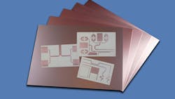
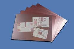
For instance, Tlam SS HTD03 thermally conductive PCB materials from Laird Technologies possess a thermal conductivity of 2.2 W/mK and low thermal resistance of 0.049°C-in.2/W for good heat flow (Fig. 1). They consist of a copper circuit layer with high-temperature-rated dielectric material and copper or aluminum baseplate to enhance the thermal performance for circuits with power supplies or light-emitting diodes (LEDs). In spite of its thermally enhanced performance compared to standard FR-4, it can be processed in the same way.
The dielectric material of a PCB such as Tlam SS HTD03 is judged as a high-temperature material by its glass transition temperature (Tg). This parameter indicates the temperature at which a material changes from a harder state to a softer, more molten state. It is typically used to determine if a material is suitable for higher-temperature manufacturing methods, such as lead-free-solder assembly processes. Standard Tg values are typically +125°C, while higher-Tg materials have a Tg of about +145°C. Tg refers to a short-term maximum temperature and should not be considered as a top temperature for continuous use.
A safer PCB upper-temperature limit being considered for high-temperature, higher-power use is the maximum operating temperature (MOT), a parameter established by Underwriters Laboratories (UL). It refers to the maximum temperature at which a PCB can be used indefinitely without significant degradation in performance. Once a PCB is used above its rated MOT, performance can degrade and reliability may be compromised. The MOT refers to temperature and does not consider the added effects of handling high power levels and possible degradation of dielectric properties.
Delivering Digital Speed
Many different rigid and flexible circuit materials are available from numerous suppliers for narrowband and broadband RF/microwave circuit applications, with a wide range of Dk values. Specifiers typically weigh performance against cost and manufacturability when selecting a material for an application, although that selection process may become more challenging with emerging applications.
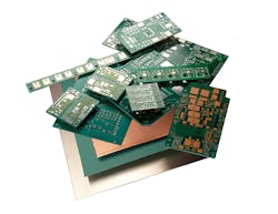
For example, automotive manufacturers are increasingly offering collision warning/avoidance systems based on millimeter-wave radar techniques. These systems require PCB materials capable of low-loss performance to 70 GHz and beyond, such as RO3003 circuit materials from Rogers Corp. (Fig. 2). These PTFE-based materials are fortified with ceramic filler for excellent electrical and mechanical stability. They feature low CTE values for all three material axes, in keeping with automotive applications. RO3003 circuit material exhibits low dissipation factor in the z-axis (0.0010 at 10 GHz). Its dielectric constant of 3.00 is controlled to a tolerance of ±0.04 for excellent electrical stability. It also has low moisture absorption for stability in high-humidity environments.
Wireless operating frequencies are expected to skyrocket with the development of fifth-generation (5G) cellular communications systems, requiring cost-effective circuit materials for use at millimeter-wave frequencies (above 30 GHz). The same properties that qualify a PCB material for millimeter-wave circuits also make it suitable for high-speed digital circuits. Conversely, the excessive loss of low-cost materials such as FR-4 results in serious degradation of performance for millimeter-wave and high-speed-digital circuits.
Circuit materials capable of high-speed-digital operation must handle signals rich in harmonic content. When the harmonic signal components of a digital signal at 10 Gb/s are considered, with third,-, fifth-, and seventh-harmonic signal components, circuit material requirements are in the same range when handling, say, analog millimeter-wave signals.
To maintain the signal integrity of input signals, a circuit must faithfully reproduce all of its essential harmonic components without distortion. In particular, material parameters related to consistency of Dk, such as TCDk, will provide insight into the material’s capability to maintain transmission lines with consistence impedance characteristics—vital for achieving high signal integrity in high-speed digital circuits.
Looking for parts? Go to SourceESB.
About the Author
Jack Browne
Technical Contributor
Jack Browne, Technical Contributor, has worked in technical publishing for over 30 years. He managed the content and production of three technical journals while at the American Institute of Physics, including Medical Physics and the Journal of Vacuum Science & Technology. He has been a Publisher and Editor for Penton Media, started the firm’s Wireless Symposium & Exhibition trade show in 1993, and currently serves as Technical Contributor for that company's Microwaves & RF magazine. Browne, who holds a BS in Mathematics from City College of New York and BA degrees in English and Philosophy from Fordham University, is a member of the IEEE.
