What You Need to Know About the Telemetry Network Standard

Members can download this article in PDF format.
What you’ll learn:
- An overview of the TmNS system with core benefits and comparison to 5G.
- Bidirectional communications is a fundamental enhancement brought by TmNS.
- While 5G is viable for flight-test telemetry, TmNS may have the edge.
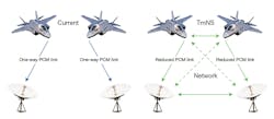
Flight-test instrumentation has changed dramatically over the last decade. Data-acquisition units (DAUs) transitioned from using protocols like pulse-code modulation (PCM) to Ethernet, which facilitates higher traffic, increased compatibility, and access to many useful features available in the commercial space (Fig. 1). The increased data and desire to gain more control over onboard systems from the ground has led to significant recent interest in using a bidirectional, Ethernet-like telemetry protocol. The industry is investigating commercial protocols, such as 5G, for such a role.
Another standard explicitly developed for telemetry, the Telemetry Network Standard (TmNS), was recently released in IRIG 106-19.1 TmNS is a new tool for the flight-test telemetry industry. This article presents an overview of TmNS, its core benefits, and a comparison to 5G.
The Telemetry Network Standard (TmNS)
TmNS aims to move telemetry into the network age, representing a paradigm shift from unidirectional PCM architectures. It hopes to increase test efficiency, utilize the available RF spectrum more efficiently, and improve the interoperability and sustainability of airborne and ground systems. The standard identifies interfaces for configuration, management, network transport protocols, telemetry link, and various other system and component capabilities.
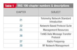
TmNS system requirements have implications for all standard flight test equipment, including DAUs, switches, recorders, radios, and ground complements such as the antenna and the ground-system software. The TmNS system is well-documented with the six chapters in the IRIG 106 standard as outlined in the table.
U.S. ranges are now rolling out TmNS-aware equipment, which is becoming operational for current flight-test programs. Only time will tell how much of the global flight-test community will adopt it, although there is a clear interest in such a technology.
The standards have high-level information with some clues to the lower-level functionality that makes the system work. Most complexity lies in the software; training programs, particularly for first-time use instruction, will be critical to a successful rollout. Those who helped develop these systems over many years and who are the hands-on users of the current products are the present experts.
Key Features of the TmNS System
Bidirectional communications are one of the most fundamental enhancements provided by the TmNS. It enables the following system capabilities:
Real-Time Access to TA Measurements and PCM Backfill
This provides a mechanism for real-time access to current and past measurements on the test article (TA), both directly from the sensors and from the recorder(s). Such access allows users to perform several practical tasks, the most beneficial of which is arguably "PCM backfill."
One of the most protracted problems with traditional telemetry has been data dropouts. These gaps in the flight-test data can occur at any point in a test flight, and they can prevent the ground controllers from knowing if a test point was completed successfully or not.
With real-time access to data stored in the recorder, a ground engineer can retrieve any past measurements. This data can then be patched back into the stream to fill in any gaps or correct corrupted data, giving the engineer a complete aggregate of data.
Real-Time Command and Control of TA Equipment
This provides the ability to status, configure, and control TA equipment from the ground station. There are features on some airborne equipment that would be useful if they could be accessed from the ground. One example is transmitters, which may respond to various commands.
For instance, a ground flight-test engineer may note that the link margin is dropping beyond a certain distance and turn on the forward error correction (FEC) to help make up some of the link distance with the FEC capability. An engineer also could change the modulation type to adjust how much data can be transmitted or change the frequency used in another range it’s flying to (range frequency allocations are often different).
Dynamic Spectrum Sharing
This allows for sharing spectrum resources among many concurrent test activities based on instantaneous demand for telemetry resources. As a result, the ground staff has a much easier job when multiple aircraft are in the sky, including between multiple ranges.
Quality of Service
QoS is somewhat like dynamic spectrum sharing, except priority can be assigned to different sources of data. They may want to ensure that anything the flight test pilot says over a voice channel gets top priority. They can do this on the fly—for example, the ground may want to communicate something meaningful with the aircraft.
Fully Interconnected System
Such a system provides the ability to seamlessly transition transmission and receipt of data from TAs from one antenna to another, including antennas in different networks (frequencies) and other ranges. The TmNS uses the term “handoff” to describe this type of transition.
The expectation is that aircraft may fly from range to range. As you leave one range, the frequency of the transponder and possibly the telemetry stream could change. The network needs the ability to switch frequencies while keeping the networks connected. The TA can talk to two different ranges at the same time until a handoff process is complete.
Over-the-Horizon Telemetry
This provides the ability to perform TA-to-TA telemetry (relay) communications to support tests involving large numbers of TAs and long distances. Depending on an aircraft’s antenna and so forth, they could relay information 20 to 30 nautical miles. Thus, multiple aircraft could create an effective long-range re-radiation system and allow for some exceptionally long-distance telemetry.
Security Protocols
With network security and access being a worldwide concern, the TmNS system is no different with access restriction and payload security for network data privacy to limit network access when required and authorized. Programs that don’t require higher-level protection will use the system with the security policy disabled. The TmNS system incorporates an AES-based encryption algorithm to provide data privacy like what Curtiss-Wright released for Chapter 4 type data with its MESP-100-1 product line.
Developing a TmNS Radio
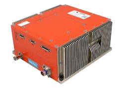
The TmNS program called for compatible DAUs, radios, radio accessories, switches, recorders, and software as seed products to grow the system. Curtiss-Wright undertook the development of many of these devices. We found the main challenges involved developing our TmNS radio, the nXCVR-3140A-2 (Fig. 2).
Beyond the typical challenges facing any complex rugged technology, this was principally due to our engineers having a lot of common knowledge of the performance and functionality of Ethernet technology. Thus, that part of the development was much more familiar than RF technology.
The nXCVR-3140A-2 IP transceiver is designed for air-to-ground and ground-to-air wireless TmNS-based communications. The transceivers work together to perform wireless router functions, transparently connecting two or more radios in a point-to-point or multipoint configuration. It implements the standards from the IRIG-106 chapters noted in the table to yield all of the proposed benefits.
The iNET transceiver uses 100/1000BASE-T Ethernet for the primary data interface. It incorporates the latest shaped-offset quadrature phase-shift keying (SOQPSK) technology and power-efficient capability to achieve maximum transmission and reception distance under harsh environmental conditions.
Burst-mode implementation of the radio has a controlled 20-Mb/s bandwidth and is filled with data to assist in maintaining the total bandwidth. SOQPSK is now widely used in the U.S. due to its maturity as a waveform and the frequency crowding that’s occurring on the U.S. spectrum.
For further reading, several papers and articles discuss the telemetry transition to C-band that’s still in process at present. The C-band provides more bandwidth to support the wider data transmissions required today as well as new product development.
Radio Metrics
The radio features several built-in tests and performance metrics for the user to determine the health of the wireless connection. Like every other higher-order electronic box, the radio metrics have a “personality” and language that needs to be understood by the user to determine what the radio is telling you and what is seen at its current location.
We suspected that, as the radio usage increases and the learning experience continues, the metrics will become a primary source for information regarding the environment in which the links are communicating. We expect the list of metrics to expand as the learning curve continues over the next few years. A sample of the list of current metrics is as follows:
- RSSI: Received signal strength in dBm.
- Eb/No: Energy per bit-to-noise spectral density ratio.
- LQI: Link-quality indication based on constellation error-vector magnitude (EVM).
- CINR: Carrier to interference-and-noise ratio based on constellation EVM in dBs from a look-up table.
- LDPC FEC errors: Packets with uncorrectable bits.
- Antenna VSWR: The antenna 50-Ω match is measured and reported if it appears the antenna connection is broken or degraded.
- GPS Lock: Critical to the operation is time synchronization between the radio communications in the system. Time is based on a provided GPS receiver module in the radio, IRIG-B time, and 1588 time. A 1-second pps timing pulse is provided out of the radio as a reference.
- Secondary voltage monitoring: There’s active monitoring of the internal voltages on the secondary power supply and reports of out-of-range results. The voltage monitoring is a new function that reports variations in the levels under normal operation of the radios in use.
The Importance of Training
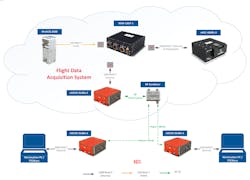
Due to the complexities of the system, training is key to its success. Curtiss-Wright has started training on the system and includes the TmNS-aware products offered by the company. A chapter in the Curtiss-Wright training is dedicated to a “quick start setup” to train the new user on setting up the radios. This includes an example traffic schedule and data to assist in understanding how to configure and use the system in a typical application (Fig. 3).
Current flight-test activity
Despite restrictions caused by the COVID-19 pandemic, system-integration flight tests were completed successfully in 2021. Perhaps with the appropriate authorizations, the results from these tests may be made public with a future follow-up paper.
TmNS and Streaming Telemetry Coexistence
Part of the use case for the TmNS is to augment the traditional streaming telemetry solution, which is a one-way link from the air to the ground. It sends key critical safety data or redundant data off the network for validation purposes. The downlink also provides a source for antenna tracking on the ground using the existing receiver equipment until a better system can be implemented. Tracking C-band is still a challenge for the current infrastructure. Until fully upgraded across the ranges, C-band will continue to be a discussion point on which lobe it’s tracking on.
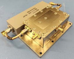
A bidirectional amplifier and filter pair (iBDA) plus diplexer can assist a user in dealing with lossy cabling and directing the RF in the right direction (Fig. 4). The iBDA will be used when combining the radio’s bidirectional RF and the single direction of the streaming telemetry link. The bidirectional amplifier is implemented with a low-noise amplifier (LNA) to overcome some or all of the cable loss when the iBDA is positioned close to the receiver antenna.
The LNA is sized to overcome 15 dB with a low-loss RF cable in C-band (4400 to 5250 MHz). The advantage of using an LNA to drive a lossy cable into the radio is the improved noise figure (NF). The radio itself has a 6-dB NF, and the iBDA LNA has an NF of 1.5 dB. With the iBDA LNA driving the lossy cable, the predominant NF is situated at the iBDA and not the radio, which enhances the performance in low Eb/No conditions present in all test-flight environments. The iBDA also comes with a bandpass filter to minimize any in-band interference.
The radio is tunable from 4400 to 4940 MHz and the bandpass filter will help resist interferers from entering the radio and possibly desensitizing the radio front-end. The filter is user-replaceable if alternate center frequencies are required.
5G vs. TmNS Radio
The industry excitement over 5G, not just from the cellphone user but also from the 5G implementers' perspective, makes this wireless network very attractive. Indeed, the similarity of 5G to the initial generation of transceivers produced by Curtiss-Wright shows how aligned it is with emerging wireless-transmission needs. The 802.11-like operation, multipath compensation, and the variable bandwidth based on the distance of that early radio were far ahead of its time frame in 2010-2014.
With the TmNS (originally iNET) program migrating from the OFDM format to a burst-mode SOQPSK modulation format, some desirable performance was retired from the features table. The program implemented a well-understood SOQPSK waveform compatible with the airborne size, power constraints, and dissipation requirements typical for modern fighter aircraft.
A 5G solution with its ground infrastructure is a viable solution for many broadband networks and well-suited for the cellphone industry with its frequency band, spatial diversity, and multipath compensation needs. In a telemetry use case, 5G will have its challenges as, in most cases, 5G uses a higher frequency band where wide channel bandwidth is available. The issue here is that the transmission distances in these bands are only some 1,500 ft. (450 m). In flight-test telemetry, it’s typical for the transmission distance to be about 130 miles (213 km), also line of sight.
5G relies on its ground infrastructure to relay the information from ground tower to tower to gain the distance, so it’s possible to extend its range. However, this would add latency as an aircraft moves down range, risking possible data loss. Many ranges also would need to install significant numbers of ground towers to gain the required range, adding a lot of expense and maintenance overhead.
Aside from the longer range inherent in a TmNS system, the TmNS airborne TA-to-TA relay can increase the data-link distance much more effectively. However, this relay distance depends on the airborne antenna-gain performance between two aircraft.
The battle between a 5G solution over the TmNS solution will undoubtedly drive new technology and solutions into the future Telemetry Range Wireless Network. It will be interesting to see how the flight-test telemetry industry puts forth its technology for a new and living wireless network system, sustainable by using the latest commercial technology in a telemetry use case. Both 5G and TmNS will evolve into a new standard, and we’re looking forward to following the developments.
Conclusion
TmNS as a documented network-based system is an emerging technology for the major flight-test ranges in the U.S. The upgraded ground infrastructure allows for bidirectional data and control. This is a significant step forward for the flight test community, with many benefits that can increase test efficiency and effectiveness.
5G certainly has its advantages and challenges as a primary wireless solution for all flight test applications. Indeed, 5G has a use case in the telemetry space, for example, offloading data on the ground. It will be interesting to examine the successes in using this commercial technology as the community starts testing it. Meanwhile, the TmNS will continue to mature as well. Curtiss-Wright looks forward to working on TmNS with future developments supporting IRIG-106 in existing and future hardware and software products.
Reference
1. IRIG STANDARD 106-19 TELEMETRY STANDARDS, 2019
About the Author
Paul Cook
Director of Missile Systems, Curtiss-Wright Defense Solutions
Paul Cook is the director of missile systems at Curtiss-Wright Defense Solutions. He has 37 years of extensive design and product-line experience in telemetry systems. He’s held both engineering and management positions in design and development, embedded encryption, RF subsystems and data links, engineering and business management, and program management. Paul has 34 years of experience in the telemetry industry and three years in Information Assurance Type I CCEP certifications.
Cook joined Teletronics in 2007 and worked in the telemetry industry for General Dynamics Corp., Aydin Corp., and L-3 Communications Corp. He obtained a BS degree from the College of New Jersey and has completed various postgraduate courses towards an MBA and Program Management Certifications.
