Understanding GNSS Correction Methods

Members can download this article in PDF format.
What you’ll learn:
- Five causes of GNSS signal inaccuracies.
- The types of GNSS corrections and when to use them.
- How to choose the optimum GNSS correction method for your products and applications.
Global navigation satellite systems (GNSS) have transformed the way both individuals and machines navigate across the globe, leading to a growing number of organizations utilizing positioning data in the development of products and applications.
GNSS technology plays a crucial role in enabling autonomous vehicles, robots, logistics fleets, and emergency-response systems to accurately determine the precise locations of people, places, and things on Earth's surface. As a result, routes are not only more accurate and efficient, but also safer.
As a satellite-dependent navigation system, various atmospheric and technological factors can impact the accuracy and precision of GNSS signals. These signals often need to be corrected by receivers before they can be used for positioning, and various correction methods exist today to do so. Each method has its own advantages and disadvantages, catering to diverse accuracy requirements and application scenarios.
Five Causes of GNSS Signal Inaccuracies
When choosing the best GNSS correction method for a specific project, it’s important to comprehend signal errors and their underlying causes. GNSS errors result from a combination of elements, such as ephemeris inaccuracies, disparities in satellite clocks, conditions in the ionosphere and troposphere, and inconsistencies between various satellite systems. Each signal-correction method addresses these elements differently, resulting in pros and cons that must be weighed before selecting and implementing a solution.
1. Inaccurate ephemeris data
To calculate their position on Earth, GNSS receivers need to know the exact position in space of the satellites they use. Satellite positioning and orbital parameters are represented in ephemeris data, but sometimes this data is incorrect. Ephemeris inaccuracies cause the receiver to not know exactly the satellites’ positions, impacting the intersection of GNSS signals and positioning information on Earth.
2. Differences in satellite clocks
Even the highly accurate atomic clocks on GNSS satellites can introduce errors in the timestamps used by GNSS to calculate positions. The exceptionally high speed at which GNSS satellites travel in space (approximately 7,000 mph) adds another layer of complexity for these calculations, because even a nanosecond of difference can lead to substantial positioning errors.
3. Conditions in the ionosphere
The ionosphere consists of charged particles that can affect the speed of light and radio signals as they pass through the upper layer of Earth’s atmosphere. Fluctuations in solar radiation and other ionospheric conditions may result in delays or distortions in GNSS signals, introducing measurement errors that require correction for precise positioning. Although the influence of the ionosphere can cause significant signal interpretation errors, correction methods are able to effectively model and account for them.
4. Conditions in the troposphere
Weather, which occurs in the troposphere, also impacts GNSS signals as they travel from satellites in space to receivers on Earth. Temperature, humidity, and pressure can affect the speed of light and radio signals much like the charged particles of the ionosphere, leading to even more delays and distortion in GNSS calculations. However, because weather is highly localized, tropospheric errors must be modeled and corrected from a relatively close distance to achieve the level of accuracy needed for precise positioning.
5. Group delay (code bias)
GNSS satellites are operated by different countries and organizations around the world. While they’re generally aligned, minor discrepancies in time references and frequencies exist that can impact the accuracy of GNSS positioning. Referred to as group delay or code bias, it must be corrected to ensure that signals are interpreted correctly.
Types of GNSS Corrections
Understanding the origin of errors is critical when selecting the optimal GNSS signal-correction method for a particular product or application. Each method has advantages and disadvantages ranging in importance depending on the application of GNSS positioning.
Real-time kinematic positioning
Real-time kinematic positioning (RTK) correction is widely regarded as the best method for achieving precise GNSS signal correction (Fig. 1). It requires setting up a base station with a GNSS receiver at a very well surveyed location near the target area (usually within 30-50 km), which transmits corrections to another GNSS receiver (called the rover).
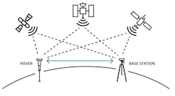
The proximity between the base station and the rover mitigates the impacts of signal errors. Any signal disparities that do exist can be analyzed to measure positional difference between the base and the rover, enabling the latter to calculate highly precise rover positions.
However, classical RTK solutions have a notable limitation: They require an extensive infrastructure of these base stations to achieve corrections over wide areas. This necessity for a dense network of base stations can escalate costs, posing a significant drawback to the implementation of classical RTK solutions.
- Best for autonomous vehicles, consumer navigation
- Sub-optimal for positioning applications in remote areas
Precise point positioning
Precise point positioning (PPP) utilizes a limited number of highly precise and accurate stations to correct GNSS signals (Fig. 2). The PPP algorithm divides the responsibility for correction between these stations and GNSS receivers.
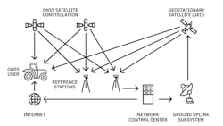
As a first step, the PPP stations model various known sources of error within GNSS, such as ephemeris inaccuracies, clock discrepancies, and group delay. They then transmit this information to GNSS receivers to conduct further calculations based on local conditions and refine the error estimation. By combining the signal data accumulated over time with the known error sources provided by the PPP stations, GNSS receivers gauge both global and localized errors (including ionospheric and tropospheric effects), ultimately calculating the necessary signal corrections for accurate positioning.
Despite its high accuracy, the limited number of existing PPP stations results in a longer time for signal correction. Using the PPP method, signal correction may take approximately 20 to 25 minutes. Particularly challenging conditions can further prolong the time needed to correct the signal, as the receiver independently calculates both ionospheric and tropospheric effects.
- Best for heavy equipment operating in water or remote locations.
- Sub-optimal for consumer GNSS receivers and autonomous vehicles
State space representation
State space representation (SSR) represents the forefront of GNSS signal-correction technology (Fig. 3). In addition to providing ephemeris, clock, and code bias-discrepancy data like PPP, SSR offers valuable insights into other signal-accuracy factors—even the highly localized interferences caused by the ionosphere and troposphere.
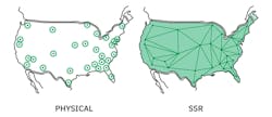
Nonetheless, many GNSS receivers lack the capability to effectively process and convert this extensive data into meaningful positions. To address this challenge, SSR data can be transformed into a virtual base station (VBS), effectively simulating an RTK base station for legacy receivers. This bleeding-edge method enables the utilization of SSR data even with conventional GNSS receivers, expanding access to high-precision positioning capabilities to more users.
- Best for the automotive and robotics industries
- Sub-optimal for teams using generic receivers
Choosing a GNSS Correction Method
As technology continues to advance, GNSS correction methods are also evolving, making high-precision positioning more accessible and reliable across a wide range of applications. However, to serve the increasing demands of organizations using GNSS for applications requiring precise positioning, correction methods must be scalable, efficient, and accurate.
Different methods for correcting GNSS signals offer varying levels of accuracy and suitability for specific applications (see table). Users must prioritize their needs, as well as the benefits and tradeoffs of each correction method, as they select which is best suited to their use case.
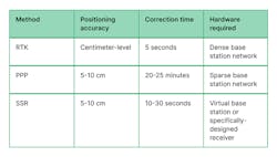
RTK produces fast, hyper-accurate results in developed areas, but it can be expensive to deploy in areas without the proper infrastructure. With PPP methodology, users in remote locations are able to access precise positioning information, but it can take a substantial amount of time. SSR is powering some of the most innovative applications in technology today, but it’s not as accessible as other methods due to legacy-receiver limitations.
Once they have assessed cost, speed, and accessibility, developers can select the GNSS correction method best suited for their product or application. As this continued innovation in the GNSS space increasingly helps organizations overcome challenges in signal correction, it will be interesting to see what new cutting-edge technology develops to shape the future of our world.
About the Author
Aaron Nathan
CEO & Co-Founder, Point One Navigation
Aaron Nathan, founder and CEO of Point One Navigation, is an entrepreneur and technical leader with over a decade of experience in robotics and critical software/hardware development. He has led multidisciplinary teams building complex systems in financial, defense, and enterprise markets and has founded two venture-backed startups. He has deep domain experience in sensor fusion, computer vision, navigation, and embedded systems, specifically in the context of self-driving vehicles and other robotic applications.
