Queensborough Community College Gets an “A” in RF
Are enough young people pursuing RF engineering as a career? It’s a question that permeates the RF/microwave industry and continues to get louder. With wireless technology more entrenched in our lives than ever before, the industry will need a new wave of engineers focused on high-frequency technology. But as I mentioned in a previous column, is the RF/microwave industry doing enough to attract the next generation of engineers? And are colleges and universities adequately preparing engineering students to enter the RF field?
One college that’s doing its part to help foster the next generation of RF engineers is Queensborough Community College, one of seven community colleges within the City University of New York (CUNY) system. Queensborough Community College is located in Bayside, N.Y., a neighborhood in the New York City borough of Queens.
Now, perhaps you were surprised to hear the name “Queensborough Community College” as a place that’s focused on RF education. However, in terms of RF capabilities, I would be willing to say that Queensborough Community College, or QCC, has tools that aren’t available in many universities.
Much of the credit for how QCC promotes RF engineering goes to Enrique Haro, who is a senior CUNY lab technician and adjunct lecturer at QCC. Haro attended QCC himself and then started to work at the school in 2014 as a lab technician while pursuing his bachelor’s degree. After completing his degree, Haro began to teach at the school.
QCC already had a long history of providing students with hands-on lab experiments (Fig. 1). However, in terms of RF test equipment, the school previously only had rather old, low-frequency equipment. One of Haro’s goals was to create a lab with modern RF test instruments to give students a better hands-on experience. That meant bringing in newer and more advanced equipment.
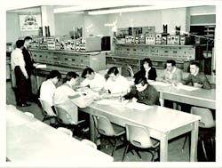
1. This picture taken in 1965 shows QCC’s electrical laboratory in the technology building.
What gave Haro the motivation to upgrade the RF lab at QCC? “I attended the same school and I took the same class,” he says. “I wish that I could have had my hands on a spectrum analyzer, but for whatever reason we had only one. The instructor did the demonstration and then asked us if we understood. That was the best we could do for a demo, but I wished that I could get my hands on the equipment.”
After Haro began teaching at QCC, he focused on bringing new equipment to the school. “I started to attend conferences and talk to field engineers from different companies because I needed to see what was out there,” he explains. “I understood that our program needed to be renewed. Our equipment only had capability up to a couple of MHz. You can only do so much with that. How were we not supporting microwave frequencies? So, we needed to bring up our curriculum to make it closer to what’s being used in the real world.”
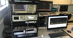
Thanks to Haro’s efforts, QCC now has industry-standard test equipment with capability at microwave frequencies. Figure 2 shows some of the equipment that QCC has in its lab. Tektronix’s RSA306B real-time spectrum analyzer and TTR503A vector network analyzer (VNA) are both included in the setup. Also in the mix are a vector signal generator (VSG), arbitrary function generator (AFG), and oscilloscope—all from Tektronix, which is lending a helping hand to QCC.
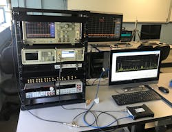
2. Here’s some of the equipment in QCC’s lab that’s currently available to students.
“We want to prepare students for a career in RF engineering by focusing on hands-on labs and evaluations,” says Haro. “We provide students with RF equipment with capabilities typically found in the industry. In this regard, we built our RF lab with VSGs, VNAs, dual-channel AFGs, and real-time spectrum analyzers.”
Now equipped with modern RF test equipment, QCC can provide students with effective hands-on lab experiments. Haro notes, “We develop laboratory experiments that cover RF fundamentals applied to technologies currently used that students can relate to, while reinforcing multiple fundamentals at the same time. Whenever possible, lab experiments are performed in industrial, scientific, and medical (ISM) bands. This provides students with a realistic scenario in which factors like interference are at play.”
Haro also believes it’s important to give students access to commercial-off-the-shelf parts. He says, “We are shifting from some educational modules to using commercial-off-the-shelf components for lab experiments to familiarize students with components they are likely to work with once they become part of an organization.” QCC has built its own inventory that includes components from vendors like Mini-Circuits and JFW Industries (Fig. 3).
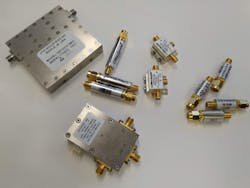
3. QCC is focused on giving students access to commercial-off-the-shelf parts. These products, from Mini-Circuits and JFW Industries, respectively, are some of what the school has in its inventory.
Haro continues, “We are moving from an all-written test evaluation during the semester to a two-part evaluation. This involves one written part for problem-solving and calculations and a second part for a hands-on evaluation in which students use off-the-shelf components and utilize the equipment to solve an RF problem.”
In one experiment, students receive a hands-on introduction to VNAs. Here, students must first build a simple filter (Pi or T network) by soldering components onto a printed-circuit-board (PCB) themselves. The PCBs are built in-house, since QCC has its own equipment from LPKF (Fig. 4).
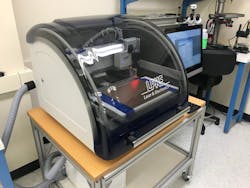
4. Thanks to this equipment, PCBs can be manufactured in-house.
After measuring their own filter, students must then measure a Mini-Circuits bandpass filter. In the end, students not only get introduced to VNAs and filters, they also get to solder themselves (which is not always a pretty sight) (Fig. 5).
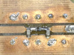
5. It may not always look pretty, but students get the opportunity to solder components themselves.
A later lab experiment that covers frequency conversion incorporates the filters built in the VNA experiment (at least the good ones). The setup was already shown in Figure 2. “Students are presented with an RF signal that’s broadcast in one of the ISM bands,” explains Haro. “They need to downconvert the signal to drive an analog-to-digital converter (ADC). Students must choose a mixer and a filter that will help them isolate the frequency of interest. They also need to determine a low- or high-side injection for the local oscillator (LO). Students then print the spectrum with markers to denote the RF, LO, sum, and difference frequencies.
“And lastly, the signal of interest, which is AM modulated, has to be characterized in the frequency domain (Fig. 6). Students must write the mathematical expression for the modulated signal. In the end, students are evaluated on their answers, performance, and confidence.”
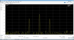
6. In the frequency-conversion experiment, students are able to view the spectrum of the mixer’s output using the RSA306B spectrum analyzer and SignalVu-PC software.
Needless to say, QCC is taking RF education very seriously. Students who begin their RF journey there have the luxury of getting their hands on modern test equipment that isn’t found at every school. If you’re looking for a college that’s trying to help cultivate the next generation of RF engineers, QCC is one place doing just that.

