This file type includes high resolution graphics and schematics when applicable.
When reading on the internet about baluns, a distinction that will often come up is “current” baluns versus “voltage” baluns. I’ve always found this distinction confusing, because an electromagnetic wave converted by a balun from differential to unbalanced modes consists of both current and voltage waves. They interplay to make a single electromagnetic wave. I can understand the terms applied to transistors—i.e., the current-driven BJT versus the voltage-driven FET—since in this case the charges are either transmitted across the junction (current) or they only create a field (voltage).
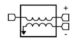
If you really want to learn a lot about baluns, you need to talk to amateur radio operators. Jerry Sevick was probably more obsessed with baluns than anyone else in history. This means that the modern understanding of baluns is as viewed through the lens of antenna operation. The roots of the terms voltage balun and current balun trace to an article by Roy W. Lewallen, call sign IVTEL, in the ARRL Antenna Compendium, “Baluns: What They Do And How They Do lt.” In it, Lewallen describes the following two baluns, and differentiates one as the “current” balun, and one as the “voltage” balun:
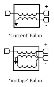
The second balun is Fig. 2 from Ruthroff's seminal and diminutive named paper, “Some Broad-Band Transformers.” The connoisseur will recognize this as a compensated version of the above 1:1 balun. Lewallen describes this as a voltage balun, since the extra line forces the voltages at the output to be equal and opposite, regardless of what the impedances are.
I believe there are two problems with Lewallen’s analysis: one that is sort of his fault and one that is not. First, Lewallen points out in his paper that the issues arise with the different types only when the impedances are unmatched between the differential ports, as one would see with an antenna but not in many of the modern high speed differential setups that Marki baluns are suited for.
Second, it is based on a DC analysis, assuming that the voltages are not time varying. This is true at the low frequencies Lewallen was working at, but it breaks down for transmission line transformers generally. Also the impedance mismatches can cause reflections at higher frequencies that break down the “current” balun argument.
In conclusion, I think that these distinctions may be valid and meaningful for low frequency baluns used in amateur radio setups, but for high-speed test baluns the most useful metric is not voltage versus current, but how much isolation is there.
This file type includes high resolution graphics and schematics when applicable.
About the Author
Doug Jorgesen
Application Support / Engineering Manager
As the application support and engineering manager for Marki Microwave, Doug is responsible for customer education, technical support, product roadmap guidance, business development, and marketing for our existing and developing product lines. In this role he interfaces with customers on technical issues and identify opportunities for Marki to grow their technical leadership.
Doug received a Ph.D. in photonics with an emphasis on fiber optic communication systems from UC San Diego in 2010. His interests include broadband communications systems over fiber or wireless media and advanced radar and electronic warfare system architectures.
