Over-the-Air Testing for 5G mmWave Devices: DFF or CATR?
Download this article in PDF format.
With the advent of 5G millimeter-wave (mmWave) devices of various sizes and applications, each requiring different architectures and sizes of mmWave antennas, it’s critical for test engineers to understand the differences in over-the-air (OTA) test chambers and test techniques. Direct far field (DFF) and compact antenna test range (CATR) are two types of OTA test methods supported by the 3GPP TR 38.810 Study on Test Methods for 5G FR2 (mmWave bands) devices.
Since CATR OTA chambers can cost up to 10 times more than DFF chambers, a test engineer must decide which one is best suited for the intended application and test requirements. Here, we will explain the differences between DFF and CATR chambers and the tradeoffs in cost and path-loss performance between the two types of chambers.
Introduction
5G mmWave devices operating above 24 GHz incorporate millimeter-sized antenna arrays or dipole antennas, which become an integral part of the device module packaging. Thus, the only way to characterize and test the performance of the antennas as part of the final product is via OTA testing.
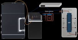
Figure 1 shows a user-equipment (UE) device (i.e., smartphone) with two built-in 5G mmWave modules, each containing a 1-×-4 patch antenna array and four dipole antennas. For this discussion, we will consider either the module or the final product as the device under test (DUT). For the example shown, each patch antenna element can have a vertical (V) or horizontal (H) polarization radiation pattern, which transmits or receives electromagnetic (EM) waves in either the vertical or horizontal direction.
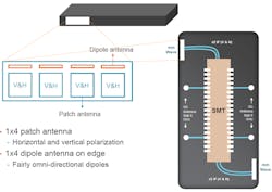
1. This user-equipment device is fitted with mmWave antennas.
When the antenna module is inside the final product, say, the smartphone, the antenna radiation pattern can be altered slightly due to the interaction with the final product enclosure materials and other surrounding components. Thus, the antenna performance, including its beamforming characteristics, needs to be tested using an appropriate OTA chamber of size, architecture, and shielding performance that ensures accurate antenna-radiation-pattern measurements.
5G mmWave OTA Test Methods
The 3GPP standards organization has published a technical document, TR 38.810, on 5G NR test methods.1 It has declared that for UE RF test methods at mmWave frequencies, the following general aspects apply:
- OTA measurement is the testing methodology
- Permitted test methods are:
- DFF
- Indirect far field (IFF), also known as CATR
- Near-field to far-field transform
The test engineer’s choice of the appropriate test method (DFF versus CATR, for example) has major implications in terms of capital equipment cost. CATR OTA chambers can cost as much as 10 times more than DFF OTA chambers. For all OTA test methods explained below, it’s the responsibility of the UE manufacturers to “declare the antenna array size.”
Direct-Far-Field Test Method
Typically, the exact locations of the antenna modules inside the UE DUT are well known. The DUT radiating antenna aperture dimension (D) is also known (expressed in cm). From this dimension, the required far-field distance (R) that separates the DUT from the test horn antenna can be derived using well-known mathematical equations, as explained later.
Per the TR 38.810 permitted test methods, if D ≤ 5 cm, the DFF test method can be used. This can translate to a significant OTA chamber capital cost savings. For example, a typical UE smartphone antenna module for UE smartphones, operating at both the 28- and 39-GHz frequency bands, has a D dimension of just below 3 cm—well within the “D ≤ 5 cm” requirement for the DFF chamber test method.
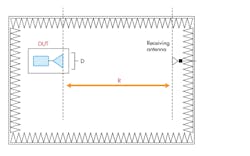
2. Here’s a representation of a DFF OTA chamber. (Source: Ref. 2)
For DFF (Fig. 2), the far-field distance (R) is the minimum distance at which the spherical waves can be considered as a “plane” wave at the receiving test antenna, thus fulfilling the following mathematical requirement:

where D is the diameter of the smallest sphere that encloses the radiating part of the DUT.
For D = 5 cm, the above equation yields a minimum far-field distance (R) of about 47 cm at 28 GHz. With the above equation, it can be shown that a 60-cm DFF OTA chamber, such as the one shown in Figure 3, satisfies the DFF test method requirements for a final product that has 5G antenna modules with apertures (D) of up to 4.5 cm at frequencies up to 44 GHz. Therefore, for existing 5G mmWave modules with D in the range of 3 cm, the DFF OTA chamber is the most economical choice.
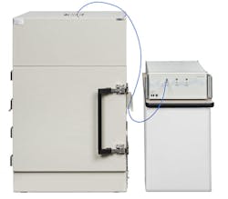
3. A 60-cm DFF OTA chamber is shown with LitePoint’s IQgig-5G mmWave tester.
Indirect-Far-Field Test Method
The IFF test method creates the far-field environment using a transformation with a parabolic reflector. This is also known as CATR.
Inside the CATR chamber, the DUT radiates a wave front to a range-antenna reflector that then collimates the radiated spherical wave front into a receiver-feed antenna (Fig. 4). The separation between the DUT and the receiver is enough so that the emanating spherical wave reaches nearly plane phase fronts from transmitter to receiver.2
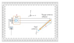
4. This drawing represents a CATR OTA chamber.
Per the 3GPP TR 38.810 document cited earlier, the CATR chamber test system does not require a measurement distance of:to achieve a plane wave, as is the case with the DFF range. For CATR, the far-field distance (R) is seen as the focal length; that is, the distance between the “feed antenna” and the parabolic reflector. It’s calculated using the following equation:
R = 3.5 × size of reflector = 3.5 × (2D)
For D = 5 cm, the CATR far-field distance, or focal length, is 3.5 × 2 × 5 = 35 cm, which allows for a more compact OTA chamber at the expense of a high-precision parabolic reflector.
Near-Field to Far-Field Transform Test Method
The near-field to far-field transform test method computes the performance metrics defined for far field by using mathematical near-field to far-field transformations. Thus, the UE radiated near-field beam patterns are measured first. Next these measurements are translated into far-field metrics using the near-field to far-field mathematical transform.
Per TR 38.810, the near-field to far-field transform test method is only applicable for DUTs with radiating apertures of D ≤ 5 cm. A near-field to far-field transform test chamber can be smaller than DFF and CATR chambers, since the DUT is tested in the near field.
DFF vs. CATR OTA Path-Loss Comparison
As discussed in Ref. 3, OTA path losses can represent up to 94% of the total link budget in the OTA test setup. Thus, minimizing such path loss is of critical importance for the test engineer.
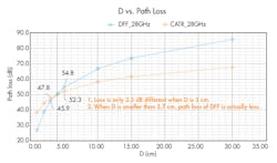
5. These plots compare DFF and CATR path loss at 28 GHz.
Figure 5 plots the path loss versus antenna aperture size (D) for both DFF and CATR OTA chambers. The path loss in dB is calculated using the Free Space Loss formula, with R = far-field distance:

From Figure 5, at 28 GHz, the path loss is actually less for a DFF chamber when D ≤ 3.7 cm as compared with the path loss of a CATR chamber. As mentioned earlier, typical 5G UE antenna array modules have an aperture D in the range of 3 cm. Thus, the DFF OTA chamber is a better choice than the CATR OTA chamber in terms of path loss for D ≤ 3.7 cm.
Figure 6 compares the OTA path loss at 28 and 39 GHz for both DFF and CATR for D = 2.78 cm, the approximate dimension of a 1-×-4 antenna array for UE applications. As can be seen, the path loss of a DFF chamber is less than or equivalent to that of the CATR chamber at the same frequencies for the same DUT.
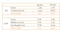
6. DFF and CATR path loss are compared at 28 and 39 GHz for D = 2.78 cm.
Conclusion
The choice of OTA test methods, DFF versus CATR for example, has significant implications on capital cost and path-loss performance. For UE DUTs that have built-in antenna arrays with D ≤ 3.7 cm in well-known locations inside the DUT, the DFF OTA test method yields capital-expenditure savings that are up to 10 times greater than the CATR method, with equivalent or lower path loss.
Jeorge S. Hurtarte works in product marketing and Middle Wen is Product Manager at LitePoint.
References
- 3GPP TR 38.810. 3rd Generation Partnership Project; Technical Specification Group Radio Access Network; NR; Study on test methods; (Release 16).
- 3GPP TR 37.842. 3rd Generation Partnership Project; Technical Specification Group Radio Access Network; Evolved Universal Terrestrial Radio Access (E-UTRA) and Universal Terrestrial Radio Access (UTRA; Radio Frequency (RF) requirement background for Active Antenna System (AAS) Base Station (BS; Release 13).
- Link-budget calculations: Needed for 5G OTA testing. Jeorge Hurtarte - January 22, 2019.

About the Author
Jeorge S. Hurtarte
Product Marketing

Middle Wen
Senior Product Manager
Middle Wen graduated from National Chiao Tung University in Taiwan with a master’s degree in communications engineering. Since joining LitePoint in 2015, he’s been responsible for managing 5G/cellular signaling and non-signaling RF test solution products. With over 17 years of experience in the wireless communications field, Wen has in-depth knowledge and insights into the development and application of wireless communication technologies.
