The Critical Role OTA Testing Will Play in 5G

Download this article in PDF format.
In comparison to 4G, the fifth-generation (5G) mobile network is designed to deliver three primary use cases: the capacity to transmit/receive more data, improve responsiveness, and connect millions of devices at once. More specifically, this includes enhanced mobile broadband (eMBB), ultra-reliable, low-latency communications (URLLC), and increased connectivity to allow billions of devices and applications to come online seamlessly and communicate simultaneously.
Over-the-air (OTA) measurements are an essential part of the performance evaluation and certification of these wireless devices by measuring the transmit power and receiver sensitivity performance. With 5G moving from the research and development phase and into deployment, OTA testing for design validation and/or volume production becomes a more critical task. Network operators and device original equipment manufacturers (OEMs) must be able to evaluate and certify the reliability and performance characteristics of devices and base stations in environments that closely resemble those in which they are actually used.
OTA Overview
As 5G mobile technology evolves to millimeter-wave (mmWave) frequencies of 28 GHz, 39 GHz, and beyond, several drivers will necessitate OTA testing. At mmWave frequencies, signal-absorption rates are much higher, requiring the need for directional transmissions/reception (beam focusing or beamsteering) to boost the gain. Beamsteering will be a key feature in the context of 5G. It’s a significant challenge to test the beamsteering capabilities of base stations and user equipment in every phase from research and development through production.
Only test systems that can handle 3D center-of-beam and off-center-of-beam measurements in a radiated environment with extremely accurate positioning systems can properly characterize a 5G device. This includes measuring EIRP/EIS, beam-transmit signal quality, beam-receive performance, beam-acquisition timing, and beam-tracking performance. It also involves side-lobe measurements that affect total radiated power, including in-band and out-of-band spectrum-emissions-related performance.
The level of component integration of a commercial 5G mmWave-capable device under test (DUT) will increase significantly over previous generations, making it almost physically impossible to connect the DUTs to the test equipment by cables. And even if cables could be connected, cable costs and cable losses at mmWave frequencies would be prohibitive. DUT fixtures supporting mmWaves can be extremely fragile. Consequently, test points such as those in the signal path from the output of a power amplifier to the input of an antenna will no longer exist.
Conducted measurements, i.e. measurements that are performed while the DUT is connected to the measurement equipment via cables, will be mainly replaced by OTA measurements, i.e. measurements of electromagnetic (EM) radiation. Test setups are needed for beam characterization and to check beam acquisition and beam-tracking performance. Only OTA test systems will provide this capability.
OTA testing of wireless devices is required by numerous regulatory agencies, standards organizations, industrial bodies, and carriers. To have global access and interoperability of mobile systems, certification tests have been developed so that manufacturers around the world provide the same level of quality in all new mobile devices. The CTIA (Cellular Telephone Industries Association) has set standards for OTA testing of 3G and 4G LTE devices and has certification labs all around the world.
Minimum performance requirements for OTA behavior have previously been defined in terms of radiated power levels during transmission and receiver sensitivity levels so that all calls are received under predefined circumstances. This will certainly need to happen in 5G device testing as well, especially in the U.S., where wireless carriers have also established industry performance requirements that must be met before a new device is permitted to run on its network.
OTA Testing Presents Challenges
Several challenges exist related to OTA measurements and setting up an OTA test system for design validation and/or volume production. One set of challenges surrounds the antenna system. As the technology advances toward 5G systems, finding the proper setup and positioning for the 3D antennas to test the moving beams, while accounting for interference and scattering, will be difficult.
A new measurement dimension—space, or power versus direction of departure—must be included. One factor that the devices must account for is the blocking effect of the human body on the radiation pattern by using phantoms during OTA tests. OTA tests that measure the 3D antenna pattern can be performed in either near field or far field. Measurements in near field allow for smaller anechoic chambers. However, they require setups capable of measuring both phase and amplitude with high location precision and additional post-processing for the near-field to far-field transformation.
Another challenge is that each individual transceiver in the active antenna system needs to be characterized through an OTA interface, with measurements made for both the transmitter and the receiver. It’s necessary that each transceiver turn on for individual verification or a set of transceivers turn on for joint assessment.
A third challenge relates specifically to beamforming, which will be used heavily in 5G. Due to the high path loss and limited range of a mmWave wireless system, precise beam generation and thus tracking and fast acquisition is required for mobile users. With antenna implementations for existing cellular technologies, static pattern characterization was sufficient. However, mmWave systems will require dynamic beam-measurement systems to accurately characterize beam tracking and beamsteering algorithms (see figure).
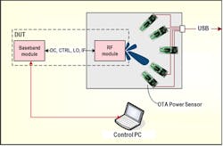
This block diagram outlines an OTA test setup for a mmWave system.
A unique set of other challenges surrounds testing the devices for RF conformance, which today relies on well-characterized cabled test port connections to enable repeatable measurements. Such a test setup and the necessary calibration needs to be defined in an OTA environment due to the lack of connectorized RF test ports in 5G devices.
A similar challenge arises during volume production. Radiated device tests must be performed for every wireless-enabled device. Given how rapidly devices are produced, OTA test systems will need to be flexible and quickly adapt to meet the testing needs of future and unforeseen devices without sacrificing any quality or depth in the test methods. Calibration of the antenna system to ensure that the misalignment between RF signal paths is below a specified limit, as well as functional tests of the completely assembled unit, must all be performed.
OTA Testing Future is Here
Although connecting mobile devices to test equipment through cables is the most convenient and cost-effective method, it does not mimic the actual behavior of these devices in the real world. Over time, it will become less and less feasible as devices become more integrated. This presents significant challenges as mobile operators move to higher frequencies to obtain larger bandwidths for support of 5G.
To test mobile devices in situations similar to what users actually experience, the tests must be executed wirelessly or over the air. As a result, designers can see what truly happens as the radio waves propagate over the air from the user equipment to the base station and from the base station to the user equipment.
New OTA power-measurement systems are accurate, affordable, and scalable to fit most any testing requirement. OTA measurement systems must support a frequency range from 27.5 to 75 GHz, thus covering the 28- and 39-GHz bands for 5G currently under discussion, the 57-to-66 GHz band defined for WLAN IEEE 802.11ad, and frequencies greater than 66 GHz for WLAN IEEE 802.11ay.
Removing the need for expensive test fixtures, OTA power measurement systems enable DUTs to easily be interchanged without impacting test reliability and repeatability. These OTA test systems, like the NRPM power-measurement solution from Rohde & Schwarz, can easily be integrated into a shield box and used to determine the direction of beamforming.
Some OTA power-measurement systems feature an integrated diode detector to measure the power directly on the receive antenna. The number of antenna modules can be selected to scale the system to meet different test requirements. The economical base configuration with one antenna module measures the power of the incident wave from the DUT to the antenna module. More antenna modules can be added to test the beamforming function.
Conclusion
As mobile technology evolves toward 5G systems, two main drivers will necessitate OTA testing. The level of integration of the DUT will increase significantly, and it will be physically impossible to connect the DUTs to the test equipment by cables, thus requiring OTA testing. Secondly, at mmWave frequencies, signal-absorption rates are much higher, requiring the need for beam focusing or beamforming to boost the gain.
OTA testing will be a game-changer for 5G networks. It’s a prerequisite for the new mobile device and network designs and their certification. For 5G test systems, the basic components are expected to remain essentially the same, but they must be adapted for the higher frequencies.
Lawrence Wilson is Product Manager at Rohde & Schwarz.

