Robust Switch Matrix Eases Multichannel Testing
This file type includes high resolution graphics and schematics when applicable.
Modern components and subsystems—whether in commercial or military applications—must often be tested for a multitude of different characteristics, often requiring disparate test systems to make the required measurements. This can be done by loading a device under test (DUT) into a test fixture and physically moving it from test system to test system.
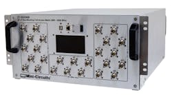
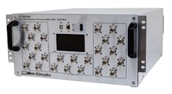
However, there is an easier way: Use a switch matrix with the capacity and performance to make the connections between the DUT and the different test systems electronically, such as the model ZT-20X6NB 20 × 6 nonblocking switch matrix from Mini-Circuits. With a bandwidth of 600 to 6,000 MHz and enough ports to connect a slew of test instruments/systems at one time, it even includes a front-panel touchscreen for easy on-the-spot control.
Better still, the ZT-20X6NB boasts enough digital interfaces for connection to almost any PC. This switch matrix has been built to last, with excellent long-term reliability and minimal degradation in electrical performance, even after millions of switching cycles.
For those who may have considered Mini-Circuits “only” a supplier of cost-effective RF/microwave components, the ZT-20X6NB (see figure) shows another side of the firm’s engineering capabilities. Housed in a solid aluminum 5U-high, 19-in.-wide rack-mount chassis, this subsystem is designed to take on the everyday punishment of high-volume measurements in a test laboratory or production line.
Removing the cover reveals a true high-frequency subsystem design and layout, containing many of the company’s components. Peering into the heart of the unit shows great attention to detail regarding component placement, coaxial interconnections, and thermal management. The fan-cooled switch matrix can handle input signal power levels to several watts (+36 dBm) to accommodate a wide range of communications components and systems testing through 6 GHz.
The ZT-20X6NB creates bidirectional signal paths, with an almost unlimited number of port-to-port combinations. These can be set from the front panel—via Mini-Circuits’ user-friendly graphical-user-interface (GUI) program—or else programmed using the ActiveX and .NET APIs provided with the switch.
In fact, all six A ports can be combined to the same B port simultaneously, as might be done for multiple-input, multiple-output (MIMO) system testing. The switch matrix has both USB and Ethernet control interfaces for remote control and programmability via an external PC with internet access, using CloudShell software.
In terms of performance, the ZT-20X6NB switch matrix is rated for +36 dBm maximum average power into any A port and +26 dBm maximum average power into any B port. The typical return loss is 12 dB across the full frequency range. The typical isolation is 80 dB between any two A ports; 30 dB between any pair of B ports connected to the same A port; and 80 dB for any pair of B ports when connected to different A ports.
The ZT-20X6NB 20 × 6 switch matrix is a well-built signal-routing solution for automated testing of multiple communications channels with a number of test systems. When one ZT-20X6NB is not enough, multiple matrices can be combined for truly high-volume signal interconnections. The unit measures 19.00 × 8.73 × 20.18 in. It is designed for 90- to 260-V ac, 47- to 63-Hz supplies.
Mini-Circuits, P.O. Box 350166, Brooklyn, NY 11235-003; (718) 934-4500

This file type includes high resolution graphics and schematics when applicable.
About the Author
Jack Browne
Technical Contributor
Jack Browne, Technical Contributor, has worked in technical publishing for over 30 years. He managed the content and production of three technical journals while at the American Institute of Physics, including Medical Physics and the Journal of Vacuum Science & Technology. He has been a Publisher and Editor for Penton Media, started the firm’s Wireless Symposium & Exhibition trade show in 1993, and currently serves as Technical Contributor for that company's Microwaves & RF magazine. Browne, who holds a BS in Mathematics from City College of New York and BA degrees in English and Philosophy from Fordham University, is a member of the IEEE.
