This file type includes high resolution graphics and schematics when applicable.
Dynamic range is a key parameter in electronic systems, but one that is often difficult to compare at the component level when trying to design a system for optimum performance. it's a specification that is often defined at the upper limit by a conceptual parameter known as the third-order intercept (TOi) point. To fully understand the dynamic range limits of a receiver or the rF/ microwave components that form a system, it can be helpful to understand the various elements that comprise dynamic range.
Typically expressed in decibels (dB), dynamic range is the ratio of the highest signal level a circuit, component, or system can handle, in dB relative to 1 mW of power (dBm), to the lowest signal level it can handle (in dBm). Several parameters can be used to define the highest-level signal, such as the 1-dB compression point as well as the TOi point. The 1-dB compression point for an amplifier, for example, is where the linearity of the component begins to degrade. Under linear conditions, a 1-dB rise in input power will result in a 1-dB increase in output power. When the increase at the output is 1-dB less than the increase at the input, it is said to be the amplifier's 1-dB compression point.
Similarly, mixers are typically characterized by a dynamic range that has the 1-dB compression point at one end and the mixer noise figure at the other end. For passive mixers, the thermal noise or noise figure is about the same, so a mixer's dynamic range is usually determined by the 1-dB compression point. above that level, a mixer tends to generate unacceptable levels of intermodulation distortion, which can obscure low-level signals.
A general rule of thumb for passive rF mixers is that the 1-dB compression point occurs at an amplitude that is about 5 to 10 dB less than the local oscillator (LO) power applied to the mixer. many suppliers of passive rF mixers tag their products at different operating levels, such as low-, medium-, or high-level mixers, based on the amount of LO power required for operation. Definitions for what is a low- or high-level mixer can vary across the industry, but typically an LO level of about +7 dBm is used to define a low-level mixer, while LO levels of +10 and +14 dBm are typically used for medium-level and highlevel mixers, respectively.
As an example, well-known mixer supplier Mini-Circuits offers mixers with LO levels ranging from +3 dBm through +17 dBm. in general, following the rule of thumb above, mixers with a higher LO drive level will yield a higher 1-dB compression point and, thus, a higher receiver dynamic range.
When mixers are compared by intercept point, it is important to standardize on either input or output intercept points for the comparison. in either case, a high intercept point denotes a mixer that will deliver a high dynamic range, since it can handle higher signal levels before producing intermodulation distortion that obscures the desired signal.
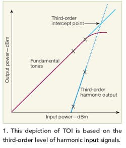
Where 1-dB compression is an actual operating point, the TOi of a receiver, mixer, or amplifier is a mathematical concept. it relates the nonlinear products of the third-order nonlinear term of a Taylor series expansion to the linear output signal of a component such as a mixer or amplifier. in some cases, a component's linearity may also be defined by its second- order intercept point, which uses the second-order terms of a Taylor series expansion, although the TOi is a much more useful parameter since it refers to blocker or jammer signal levels that fall close to the fundamental signal of interest. Because it is close to the desired signal, it is difficult or impossible to remove by filtering without attenuating the desired signal.
In a receiver, the dynamic range extends from its TOI point at the high level end to the sensitivity at the low-level end. The TOI is a result of signal saturation and distortion effects, while the sensitivity is impacted by the thermal noise of the operating environment and the receiver's noise figure, spurious levels, harmonics, and phase noise. A receiver's dynamic range is greatly dependent upon the mixers and amplifiers in the system, but can also be limited by both active and passive filters in the signal chain.
An automatic-gain-control (AGC) circuit in the front end of a receiver can be useful in avoiding signal saturation and spurious signal generation. In test equipment that is similar to a measurement receiver with a display screen, such as a spectrum analyzer, the displayed average noise level (DANL) is typically used to denote the bottom end of the dynamic range.
Sensitivity can sometimes be misleading. Receiver sensitivity may suffer in the presence of large signals, for example. When comparing receivers, one with enhanced sensitivity may not do as well with low-level signals than a less-sensitive receiver when in the proximity of high-level signals. Typically, it is the dynamic range that must be consulted in making the comparison, since a receiver with poor sensitivity but excellent dynamic range may handle low-level signals without degradation from intermodulation distortion better than a receiver with high sensitivity but inferior dynamic-range performance.
In terms of sensitivity, receivers sometimes use a figure of merit known as minimum discernible signal (MDS), which is a signal level equal to the noise level and usually specified in dBm. Since the noise level is dependent upon the analysis bandwidth of a receiver or spectrum analyzer, analysis bandwidths should be normalized when comparing units by MDS values.
About the Author
Jack Browne
Technical Contributor
Jack Browne, Technical Contributor, has worked in technical publishing for over 30 years. He managed the content and production of three technical journals while at the American Institute of Physics, including Medical Physics and the Journal of Vacuum Science & Technology. He has been a Publisher and Editor for Penton Media, started the firm’s Wireless Symposium & Exhibition trade show in 1993, and currently serves as Technical Contributor for that company's Microwaves & RF magazine. Browne, who holds a BS in Mathematics from City College of New York and BA degrees in English and Philosophy from Fordham University, is a member of the IEEE.
