Perform Effective Passive-Intermodulation Measurements
Passive intermodulation (PIM) can occur as a result of the presence of two or more high-power signals in a system. Electrical nonlinearities within a system can unintentionally act as mixers, thereby causing PIM to occur. These nonlinearities can result from loose connections, contaminated or corroded metal surfaces, ferromagnetic metals, and many other factors. It is therefore important to perform testing to verify PIM performance. In the application note, “Introduction to PIM Testing,” AR RF/Microwave Instrumentation describes a test setup that can be used to measure PIM.
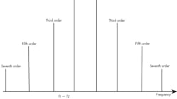
PIM is particularly problematic when both the receive signals and transmit signals in a system share a common transmission path, such as a coaxial cable, coupler, or antenna. Two high-power signals at different frequencies within the transmit band can mix with one another, potentially creating an intermodulation (IM) product that lies within the receive band. Satellite-to-ground communication, for example, transmits very-high-power signals while utilizing highly sensitive receivers. If preventative measures are not implemented, PIM can result from these high-power transmission signals. This distortion can then mask the sensitive receive bands.
A block diagram of a PIM test setup is provided in the application note, demonstrating the components used in the configuration. The setup is suitable for the testing of a two-port component, such as a cable or filter. In addition, antenna testing can be achieved with this setup with the incorporation of an anechoic chamber.
The application note emphasizes the importance of ensuring that the test setup itself does not corrupt PIM measurements. For example, the filters, couplers, and interconnects in proximity to the device-under-test (DUT) must have superior PIM performance. Coaxial cables and connectors can be a problem, as their PIM performance can degrade with use. High-power loads can also generate PIM, so they need to be considered as well. When measuring antennas, the anechoic chamber’s PIM performance is also significant. Lastly, the document concludes with a description of AR’s one-box solutions, which can provide customers with a PIM test solution.
AR RF/Microwave Instrumentation, 160 School House Rd., Souderton, PA 18964-9990; (215) 723-8181.
