RF Power MOSFETs Get Put to the VSWR Test
To ensure proper operation under a variety of real-world conditions, RF power MOSFETs can undergo voltage-standing-wave-ratio (VSWR) testing to reveal considerable details about their failure modes. Such testing alerts designers to weakness in the device while enabling the development of a more rugged design. In “Application Note 1820: VSWR Testing of RF Power MOSFETs,” Microsemi discusses these VSWR test failure modes as well as a new VSWR ruggedness test method.
This file type includes high resolution graphics and schematics when applicable.
Three dominant failure modes are produced from various load conditions under the VSWR testing of RF power MOSFETs. Over-voltage failure of either the periphery or die body can be avoided by using a nominal supply voltage fit for the amplifier circuit’s class of operation. Thermal over-dissipation failure, which arises when the safe operating area (SOA) of the device is exceeded, is inevitable at some point of operation. This failure is a function of the inefficiencies of an amplifier under certain phases of the reflection coefficient of the load. Latch-up, which is sometimes difficult to distinguish from over-voltage failure, is a product of the bipolar elements within an RF power MOSFET that can cause device failure.
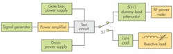
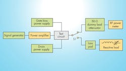
A typical VSWR test uses a gate and drain power supply to bias and power the device under test (DUT). A signal generator boosted by a power amplifier is often used to drive the DUT. To induce the various ranges of reflection, a load switch between a 50-Ω dummy load attenuator and RF power meter with a loss pad routed into a reactive load are used. To test latch-up, an unclamped-inductive-surge (UIS) test is performed using an inductor between the supply and drain voltage of the MOSFET. The inductor is charged while the gate is on. When the gate is switched off, the inductor surges power into the device.
To de-embed the changes in efficiency and power dissipation in the test amplifier from the voltage breakdown failure, which results from VSWR testing, a 20% duty pulse of 200 µs can be used. For phase adjustment, a split variable capacitor in a tunable, dual-LC network could replace several lengths of coaxial line, which is the traditional approach. This method would enable the VSWR test to reach nearly 100% reflection efficiency with reasonable Q inductors at nearly any phase angle.
See “Microsemi VSWR - Load Mismatch Ruggedness” https://www.youtube.com/watch?v=bMEsEATudgM
Microsemi, 1 Enterprise, Aliso Viejo, CA 92656, (800) 713-4113, www.microsemi.com
About the Author
Jean-Jacques DeLisle
Jean-Jacques graduated from the Rochester Institute of Technology, where he completed his Master of Science in Electrical Engineering. In his studies, Jean-Jacques focused on Control Systems Design, Mixed-Signal IC Design, and RF Design. His research focus was in smart-sensor platform design for RF connector applications for the telecommunications industry. During his research, Jean-Jacques developed a passion for the field of RF/microwaves and expanded his knowledge by doing R&D for the telecommunications industry.
