Triggering: The Digital Edge Over Analog
What you’ll learn:
- Differences between digital and analog triggering.
- Advantages of digital triggering.
- How to tell what type of triggering is used by an oscilloscope.
An oscilloscope’s trigger function, which synchronizes the horizontal sweep with the input signal, is crucial for clear signal analysis. The better the triggering system, the less time you need to spend trying to isolate rare events. Basic trigger controls stabilize repetitive waveforms by repeatedly displaying a selected portion of the input signal. Advanced trigger controls allow you to isolate specific events, optimizing sample rate and record length.
Digital vs. Analog Triggering
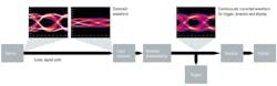
Most oscilloscopes still have an analog triggering architecture. There’s a data path for the incoming signal and a separate path for triggering. Newer oscilloscope architectures use digital triggering, which combines the two paths into one (Fig. 1).
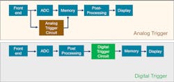
Analog triggering relies on analog circuitry to analyze the incoming signal and determine when to trigger the acquisition. The signal path is separated from the trigger path to ensure that the trigger circuitry operates independently. Oscilloscopes with analog triggers typically detect events based on voltage levels, slopes, or pulse widths, using adjustable thresholds and trigger modes such as edge, pulse, or video.
Digital triggering architectures utilize a single shared path for both the signal and triggering functions. This means that the incoming waveform is digitized and digitally processed to determine the trigger condition.
The trigger circuitry operates directly on the digitized data, allowing for a more precise and flexible triggering mechanism. Digital triggers can leverage advanced algorithms and sophisticated mathematical functions to detect events based on complex conditions, such as specific data patterns, glitches, or runts.
Advantages of Digital Triggering
Digital triggering holds a number of advantages over analog triggering, including:
- Greater trigger sensitivity
- User hysteresis control
- Wider range of filters
- HD mode applied on trigger
- Interpolation
- Lower trigger jitter
Trigger sensitivity refers to the minimum signal amplitude required for an oscilloscope to accurately detect trigger events (Fig. 2). This is important because superior trigger sensitivity allows you to isolate and trigger on small signals. It’s typically specified in terms of vertical divisions on the oscilloscope display.
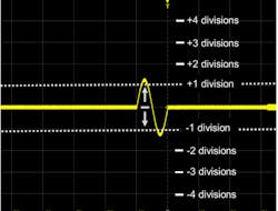
For example, modern oscilloscopes like Rohde & Schwarz's MXO 4 have a high trigger sensitivity of 0.0001 div. As a result, when the setting is 10 mV/div (and the full vertical height is 100 mV), the oscilloscope can trigger on a signal with an amplitude of 10 µV.
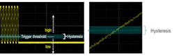
An oscilloscope’s trigger threshold is the level a signal must exceed for the oscilloscope to recognize it as a trigger event. Hysteresis, or “window size,” introduces a window above or below the trigger level. Analog oscilloscopes typically have preset hysteresis values, while digital oscilloscopes offer both automatic hysteresis settings and user-adjustable options.
With user-adjustable hysteresis, you can eliminate false triggers from noise by setting a higher value or trigger on small changes in signal amplitude by selecting lower values. This flexibility in hysteresis adjustment allows for greater control and improved triggering performance (Fig. 3).
Oscilloscopes offer various signal filters for signal viewing. These filters can be implemented using analog hardware, digital-signal-processing (DSP) algorithms, or software. Signal-path filters don’t affect the trigger circuit for oscilloscopes with analog triggers. However, for oscilloscopes with digital triggers, filters can be applied to the trigger, the signal, or both.
An advantage of digital trigger architectures is that the displayed waveform on the oscilloscope precisely reflects what the trigger circuit is evaluating, ensuring accurate visualization and analysis. Functions like real-time de-embedding are applied before the trigger, enabling the oscilloscope to trigger on the same de-embedded signal that users see on the oscilloscope display (Fig. 4).
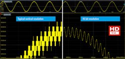
With most oscilloscopes, you can make tradeoffs between bandwidth and vertical resolution using acquisition modes. These modes average adjacent samples or apply DSP-based filters to increase vertical resolution while reducing effective sample rate. Oscilloscopes with analog triggers have a high-resolution mode, but it only applies to the signal path and not the trigger path. Scopes with digital triggers, on the other hand, offer HD mode, which allows you to improve trigger resolution and noise suppression by reducing the bandwidth (Fig. 5).
Analog triggers often have a limited threshold range with coarse increments. In contrast, digital triggers offer more flexibility—you can select any threshold value within the set vertical range. This is because the digital trigger architecture evaluates the signal after the analog-to-digital conversion and isn’t bound by bandwidth limitations.
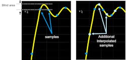
Since the information is in digital form, the instrument can make decisions based on interpolation between sampled points. This enables you to isolate minute signal details by adjusting trigger threshold and sensitivity (Fig. 6).
Oscilloscopes with analog triggers need to determine the precise time in the signal path that corresponds to the detected trigger event. This may cause trigger jitter over successive acquisitions.
Some oscilloscope manufacturers offer software correction techniques to mitigate trigger jitter. While effective in reducing jitter, these corrections need additional processing cycles, leading to slower trigger re-arm times and overall scope update rates. Oscilloscopes with digital triggers, on the other hand, have minimal trigger jitter without requiring software correction techniques (Fig. 7).

Digital or Analog: How to Tell?
Most oscilloscopes still use analog triggering. If “digital triggering” isn’t specified in the product datasheet, the oscilloscope likely uses analog trigger technology. You can also make a reliable assessment of the oscilloscope’s trigger based on other datasheet specifications.
An oscilloscope uses digital triggering if:
- It has a trigger sensitivity of less than 0.1 div. Analog triggers can’t achieve this sensitivity.
- The user can choose from a wide range of hysteresis values, from 5 div down to 0.01 div.
In addition, if an oscilloscope has a minimum trigger re-arm time in normal mode (not a special mode) measured in 10 to 100 ns, it likely has a digital trigger architecture. If you have any doubts or questions about an oscilloscope’s specifications, you should always contact the manufacturer.
Summary
The oscilloscope trigger function plays a crucial role in synchronizing the horizontal sweep of the instrument with the signal and enabling clear signal characterization. Digital triggering offers several advantages over analog triggering, including greater trigger sensitivity, user hysteresis control, a wider range of filters, the application of HD mode on triggers, interpolation capabilities, and reduced trigger jitter. You can determine an oscilloscope’s triggering technology by referring to its datasheet or asking the manufacturer.
About the Author
Joel Woodward
Oscilloscope Product Planner
Joel Woodward is strategic planner for oscilloscopes at Rohde & Schwarz. He has worked in the test and measurement industry for 27 years. Joel holds a degree in electrical and computer engineering from Brigham Young University, an MBA from Regis University, has completed course work at the Harvard Business School, and holds an FPGA debug patent. His outside interests include digital photography and hiking in national parks.
