Advanced Oscilloscopes Address Next-Gen Design Issues
This article appeared in Evaluation Engineering and has been published here with permission.
What you'll learn:
- Design challenges facing engineers today.
- An insider's look at the R&S RTO6 6-GHz class oscilloscope.
- How the instruments helps address those engineering challenges.
Designing the latest advanced products is getting more and more challenging, with many factors contributing to the difficulties. From advanced core technologies disrupting the marketplace, to the implementation and deployment of those technologies in an effective and optimum manner, having the right test and evaluation tools are an important part of the job.
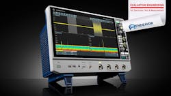
The latest benchtop engineering tools are getting more and more powerful to address the constantly increasing demands placed upon them. One example can be found in Rohde & Schwarz’s latest product introduction, the R&S RTO6 6-GHz-class oscilloscope. Offering six different bandwidth models from 600 MHz to 6 GHz, with a sample rate of up to 20 Gsamples/s, the fully integrated test solution features a high waveform update rate, excellent signal fidelity, a powerful digital trigger, and responsive deep memory (see figure).
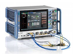
Features include a 15.6-in. full HD screen, an easy-to-use touch functionality, and a redesigned front panel to enable test engineers to quickly set up measurements. The larger screen can display a maximized waveform viewing area, and signals can be dragged and dropped to different parts of the screen with R&S SmartGrid, with access to all of the oscilloscope's applications via a single tap.
An architecture with a dedicated ASIC for optimized signal processing delivers an acquisition rate of up to one million waveforms per second, and a low-noise front end and single-core analog-to-digital converters (ADCs) with extremely small linearity errors offer a spurious-free dynamic range (SFDR) of 65 dBc, and a 9.4 ENOB. A high-definition mode increases the vertical resolution of the R&S RTO6 oscilloscopes up to 16 bits with digital filtering, also used by the digital trigger system that gives the R&S RTO6 the capability to isolate even the smallest signal details.
More than 90 measurement functions are included in the R&S RTO6 series, organized into amplitude and time measurements, jitter, eye, histogram and spectral measurements. The R&S RTO6 is now available from Rohde & Schwarz as a four-channel base instrument with bandwidth options of 600 MHz, 1 GHz, 2 GHz, 3 GHz, 4 GHz, and 6 GHz. We caught up with Tim Paasch-Colberg, product manager for the RTO6 family, to get a handle on some of the important aspects of the new series.
EE: It’s amazing how oscilloscopes have come so far. Once upon a time, an oscilloscope could do only one basic thing, and that was display and capture information. So why don't you tell me a little bit about how you see the migration of the oscilloscope into the tool that is today?
Tim Paasch-Colberg: Well, back in the day, a scope was a tool where you would measure a signal varying over time, and could display that when it was still analog. Several years ago, digital oscilloscopes became available, and they were initially running on computers. Well, once a signal gets digitized, you can do much more than just display the signal over time. Of course, you can still analyze relatively simple analog signals, and just voltage and/or current over time, but now you can do logic analysis, you can do protocol, you can do compliance tests. For example, you can measure the communication interface of your DUT and check if it's compliant with the standard you're using, or not.

The R&S RTO6, for example, also has very powerful spectrum analysis built in. With this oscilloscope, you basically also get spectrum analyzer functionality, which is already sufficient for many, many applications. Therefore, I think spectrum analysis with today's oscilloscopes is a very broad field of application now. Also, when it comes to power electronics testing, you need oscilloscopes for that. And it depends on what you actually want to measure. In some cases, you would need the signal over time and do analysis on that. In other cases you would also use spectrum analysis. For example, in EMI debugging, you typically also look at the spectrum part of your signal. With the R&S RTO6, both domains of your signal can be analyzed in parallel without compromises.
EE: Today's designer has to have a multi-tool available, because otherwise they would not be able to address all of the moving parts into these designs. So to have a tool that does everything reasonably well is far more valuable to the developer than a vertical device that is precise to three figures. The importance here is the power it's bringing to the average benchtop. I'd like to hear what your thoughts are on that aspect of it, about bringing that functionality, that level of performance that was previously inaccessible, to that price point.
Paasch-Colberg: It's a good point you're mentioning here. When looking at the EMI part, for example, every electronic device that goes on the market has to fulfill EMI standards. For that, it has to go to a test house where they have all this high-end test equipment to run the EMC test. The developer who is building a device can easily use an oscilloscope to already do some EMI debugging, to find out where sources of interference and EMI or emissions are on the board.
All of this initial finding of interference sources and so on to learn about their harmful emissions, can easily be done now with a relatively affordable oscilloscope – compared to the price of dedicated EMI test equipment at a test house. At the end, it's critical to be fast on the market for a relatively reasonable amount of money, and an oscilloscope with a very rich toolbox like the R&S RTO6 is exactly what helps them there.
EE: We've talked about the migration of the oscilloscope and how it's become a powerful tool. So now I'd like you to talk about how this represents that trend.
Paasch-Colberg: The RTO6 has a very, very broad toolbox for different applications. It's not just the “voltage over time” measurement tool, it's much more than that. Like I mentioned earlier, we have logic analysis in there, we have protocol analysis, we have compliance tests in there. We have very powerful spectrum analysis, as well as power analysis options. And on top of that, we have some functions that you need for high-speed interface testing. One example is de-embedding, which basically compensates for the effect of the measurement chain. This oscilloscope can, compensate the influence of your measurement setup on your measured signal, i.e. your cables, all the connectors, probes, and so on.
The R&S RTO6 also has a time-domain reflectometry/ time-domain transmission(TDR/TDT) functionality built in that helps you analyzing traces on your board. With everything getting faster, and signals getting quicker, and lanes on your board getting smaller, it really matters how long they are, compared to adjacent traces. On top of that, the R&S RTO6 has jitter analysis built-in. With everything going digital and going faster, jitter is becoming a very important topic.
EE: Well, the more powerful the circuits, and the more powerful the systems, you've got to be faster than that, because in order to measure something, you have to be more precise than what you're measuring.
Paasch-Colberg: That's right, you can only get the signal as precisely as your measurement device can measure. And we have been addressing this topic with the R&S RTO oscilloscope in general. We started this journey 11 years ago with our first oscilloscope, the R&S RTO1000 oscilloscope, which already had extremely good signal integrity. Over the years, we launched the second generation, the R&S RTO2000, which is still in the market, and which already had some improvements regarding signal integrity and some other things as well. And now the R&S RTO6 is the third generation of R&S RTO oscilloscopes, and it's getting better over the years.
One thing that is important for oscilloscopes is how fast you can measure. So of course, the bandwidth is telling you more or less which signal frequencies you can measure in general, which is already an indicator, how fast your signal varies over time. Another very critical topic is how fast you can acquire consecutive signal traces, that is so-called “waveforms”. Let's say: If you record one waveform now, how long does it take the oscilloscope before it can record the next waveform?
This translates into the waveform update rate of the oscilloscope, or the refresh or acquisition rate, however you call that, it has the same meaning. The R&S RTO6 reaches up to 1 million waveforms per second which is extremely fast. This is one of the major advantages of the RTO6, that itis very, very fast. So how does that help the customer?
Let's say they have a repetitive signal that is basically always the same, or very, very similar, like in a communication protocol. Now it has a glitch every other time, but you don't know how often that is. Is it once per second? Is it once every 10 seconds? Is it maybe 10 times per second, or even more than that? Well, if you want to find that out, you would typically run a mask test using an eye diagram. As long as your signal is correct, the mask is not violated – and the other way around.
Of course, you also want some statistics, for your measurement to be more reliable. So you need to record 10 million waveforms, just as an example. If you have an oscilloscope with a slow waveform update rate, you need to run this test for very long until you have these 10 million waveforms. In contrast, if you have an oscilloscope with a high waveform update rate, you are done with your test much faster. This is simple mathematics. If you have a fast oscilloscope, you can measure more waveforms in less time. This in return, gives you better statistics, also in less time. These tests are getting more and more important when it comes to communication and interface testing.
Another thing is basically the overall signal integrity. By the way, what does signal integrity actually mean? To me, signal integrity is this: How accurate is this representation of the signal shown on my oscilloscope compared to the original signal? Now, that's my interpretation.
EE: One can be over-precise and say, "The extent to the clarity of capture." You want to capture 100% of the signal. And if you successfully capture 100% of the signal, you have 100% signal integrity. So it's just saying the same thing in different words.
Paasch-Colberg: Absolutely. For oscilloscopes there are several factors and parameters that influence its signal integrity. It already starts with the probe you are using and its frequency response. Then there is the frequency response of the oscilloscope frontend preamplifier, as well as its noise level. Another factor is the shielding between channels that prevents crosstalk coming from one input channel to neighboring channel which would impair your representation of the original signal. All such factors can be optimized using high-quality analog components that for example have inherently lower noise levels and minimized crosstalk
With the R&S RTO instruments, and especially now with the R&S RTO6, we have a design with low-noise components on the front end. These help to achieve a very good signal integrity. The next component that matters for signal integrity is the analog to digital converter, the ADC. With the R&S RTO6, we have a unique ADC with minimal errors which achieves a wide spurious-free dynamic range. I don't want to go too deep into that topic, but in principle, many things need to be taken into account to achieve a good analog to digital conversion, like linearity, distortion, timing and offset errors, as well as single- versus multi-core ADCs. There are ADCs that state a high number of bits on paper, but their actual signal integrity is limited due to a multi-core architecture which increases and multiplies the mentioned errors.
For oscilloscopes, the effective number of bits (ENOB) of the overall system is a good measure for its signal integrity. Some oscilloscope might have ADCs with 10 or 12 bits, but they only achieve an overall ENOB of less than 10. The R&S RTO6 has an overall system ENOB of up to 9.4. That said, the topic ENOB and how to measure it, is quite complex. But in the end, from our point of view, it is a very good value to compare the signal integrity of different oscilloscopes.
EE: Excellent. Do you have a final thought for our audience about the device?
Paasch-Colberg: Well, we talked a lot about update rates and signal integrity. Those are basically the most important technical specifications that we want to highlight with the R&S RTO6 oscilloscope. In addition to that, it has a very broad toolbox. The R&S RTO story started 11 years ago, so there is a lot of customer input to learn from and that helped us make the R&S RTO6 even better.
About the Author
Alix Paultre
Editor-at-Large, Microwaves & RF
Alix is Editor-at-Large for Microwaves & RF.
An Army veteran, Alix Paultre was a signals intelligence soldier on the East/West German border in the early ‘80s, and eventually wound up helping launch and run a publication on consumer electronics for the U.S. military stationed in Europe. Alix first began in this industry in 1998 at Electronic Products magazine, and since then has worked for a variety of publications, most recently as Editor-in-Chief of Power Systems Design.
Alix currently lives in Wiesbaden, Germany.
