Determining Resonator Q Factor from Return-Loss Measurement Alone
It’s not uncommon to want to measure the Q factor of a resonator. One may need to determine its suitability for use in a coupled resonator filter or evaluate the performance of an RFID tag. Generally, this measurement is made with very light input and output coupling to reduce the loading effect of the 50-Ω source and load impedances.
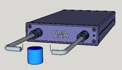
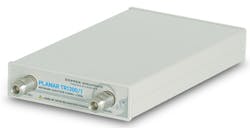
Coupling to and from the resonator might be done with two electrically short antennas or loops to couple to the electric or magnetic fields of the resonator (Fig. 1). One instrument that could make such a measurement is Copper Mountain Technologies’ TR1300/1, a 1.3-GHz vector network analyzer (VNA) (Fig. 2).
After measuring an S21 S-parameter in this fashion, the data is analyzed to extract the resonant frequency and Q factor of the resonator. The peak of the response is taken to be the resonant frequency, and then two markers are placed 3 dB down from the peak value. The peak frequency divided by the 3-dB width of the peak is then equal to the Q factor.
For example, a sweep of the circuit shown in Figure 3 results in the measurement shown in Figure 4. That graph gives us an experimental Q factor of 13.62/(13.99 − 13.28) = 19.2.
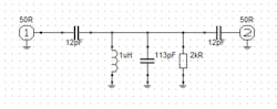
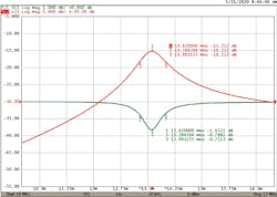
The approximate Q factor from the schematic, neglecting the effects of the 12-pF coupling capacitors and the 50-Ω source and load, is equal to the admittance of the 113-pF capacitor at 13.62 MHz divided by the conductance of the resistor, or 9.673e-03/5e-04 = 19.3. This shows that there’s reasonable agreement with the experimentally determined value.
With reduced coupling, it’s possible to obtain a slightly better measurement, allowing the S21 peak to fall to −40 dB or so to reduce the loading effect. However, the S11 reading would become very small. We will show that the Q factor may be derived from the S11 measurement, but the numbers need to be large enough to work with.
So how can this be done? Clearly, it isn’t a matter of looking for the points on the S11 curve that are 3 dB higher than the minimum. The trace shown above has a minimum of −1.6 dB, so that’s clearly out of the question. It turns out that in a lossless circuit, there’s a relationship between S11 and S21:

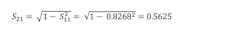
From the earlier graph we can calculate a value for S21:
If:

Then:
This S21 isn’t a real value per se, but we can still use it. Calculating the value of S21, which is 3 dB down, means multiplying by 1/√2:

Now we take that back to S11:
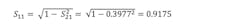
Or, −0.748 dB.
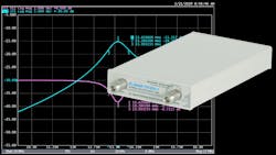
If we find this value of S11 on each side of the minimum from the earlier measurement, we get the result shown in Figure 5.
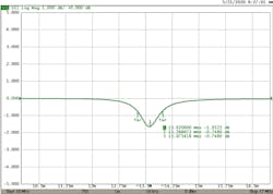
From the three frequencies shown, we can calculate the Q factor:
That result is quite close to the calculated value of 19.2.
So, with a relatively simple calculation, one can determine the Q factor of a resonator from the return-loss measurement alone.
Brian Walker is Senior RF Design Engineer at Copper Mountain Technologies.
About the Author
Brian Walker
Senior RF Engineer SME, Copper Mountain Technologies
Brian Walker is the Senior RF Engineer SME at Copper Mountain Technologies where he helps customers to resolve technical issues and works to develop new solutions for applications of VNAs in test and measurement.
Previously, he was the Manager of RF design at Bird Electronics, where he managed a team of RF Designers and designed new and innovative products. Prior to that he worked for Motorola Component Products Group and was responsible for the design of ceramic comb-line filters for communications devices. Brian graduated from the University of New Mexico, has 40 years of RF Design experience, and has authored three U.S. patents.
