Tester Reads Phase Noise To 26 GHz

This file type includes high resolution graphics and schematics when applicable.
Phase noise can cripple advanced modulation formats in modern communications systems, which is why it should be carefully characterized for the high-frequency signal sources used in those systems. Fortunately, the recently introduced model 7300 phase-noise test system from Berkeley Nucleonics can perform a variety of noise and other measurements on RF/microwave signal sources—such as oscillators and frequency synthesizers—from 5 MHz to 26 GHz while maintaining a low noise floor for enhanced accuracy.
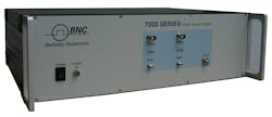
The model 7300 phase-noise test system (see figure) is a compact, single-box solution that employs proven cross-correlation procedures for reliable measurements. Such techniques are commonly used to search for short events among waveforms of longer duration. Cross-correlation measurements compare two or more waveforms that are delayed relative to one another, and the approach can be used for pulsed, modulated, and continuous-wave (CW) signals.
The measurements are well suited to comparing delayed versions of signals for different types of noise. These include amplitude-modulation (AM) noise or phase noise using the appropriate detection circuitry, such as an AM detector or a phase detector. The 7300 series phase-noise test systems include self-calibration routines and automated frequency-acquisition techniques to simplify and speed measurements.
The model 7300 phase-noise tester includes an internal frequency reference, but can also operate with an external frequency reference (from 5 MHz to 6 GHz). It can work with internal references from 2 MHz to 26 GHz with spurious levels of typically -75 dBc, and can track a device under test (DUT) over a range of ±100 ppm. It can work with external references from 5 MHz to 6 GHz at power levels from +8 to +18 dBm and tuning voltages from 0 to +20 VDC.
The phase-noise tester tackles carriers from 5 MHz to 26 GHz and measures phase-noise levels at offsets of 0.1 Hz to 1 MHz from those carriers. It works for an input power range of -10 to +20 dBm for carriers to less than 6 GHz; for 0 to +20 dBm for carriers to less than 20 GHz; and for +3 to +20 dBm for carriers from 20.0 to 26.5 GHz. The instrument itself exhibits a residual phase-noise floor of-140 dBc/Hz offset 1 Hz from the carrier; -150 dBc/Hz offset 10 Hz from the carrier; -160 dBc/Hz offset 100 Hz from the carrier; -175 dBc/Hz offset 1 kHz from the carrier; -180 dBc/Hz offset 10 kHz from the carrier; and -180 dBc/Hz offset 1 MHz from the carrier.
Its specified phase-noise measurement accuracy is ±4 dB for offsets less than 10 Hz; ±3 dB for offsets less than 1 kHz; and ±2 dB for offsets greater than 1 kHz. The test time is a function of the number of measurement points, with typical measurement times of 0.2 s for 600 points at offsets from 1 kHz to 1 MHz; 0.5 s for 800 points at offsets from 100 Hz to 1 MHz; 2.5 s for 1000 points at offsets from 1 kHz to 1 MHz; and 12 s for 1200 points at offsets from 1 Hz to 1 MHz.
The phase-noise tester provides numerous input and output connectors for signals and data, including SMA female input signal connectors, rear-panel connectors for DC power (2.5 A at 6 V), a Universal-Serial-Bus (USB 2.0) data connector, an RJ-45 local-area-network (LAN) connector (which supports an Ethernet 100BaseT LAN interface), and various power and baseband connectors. It also provides direct access to its internal Fast Fourier Transform (FFT) analyzer.
The phase-noise tester is also available with an optional GPIB connector for use in automated-test-equipment (ATE) applications, and can be programmed via SCPI Version 1999.0 control language. It weighs 9 lbs (4 kg) and can be used over an operating temperature range of 0 to +45°C.
Berkeley Nucleonics, 2955 Kemer Blvd., San Rafael, CA 94901; (415) 453-9955, FAX: (415) 453-9956.
This file type includes high resolution graphics and schematics when applicable.
About the Author
Jack Browne
Technical Contributor
Jack Browne, Technical Contributor, has worked in technical publishing for over 30 years. He managed the content and production of three technical journals while at the American Institute of Physics, including Medical Physics and the Journal of Vacuum Science & Technology. He has been a Publisher and Editor for Penton Media, started the firm’s Wireless Symposium & Exhibition trade show in 1993, and currently serves as Technical Contributor for that company's Microwaves & RF magazine. Browne, who holds a BS in Mathematics from City College of New York and BA degrees in English and Philosophy from Fordham University, is a member of the IEEE.
