Advanced Simulation Feature Combines Best of Both Worlds

When discussing simulation software, ANSYS is likely one of the first companies that comes to mind. Throughout the RF/microwave industry, engineers take advantage of ANSYS’s HFSS, a well-known 3D electromagnetic (EM) simulation software tool. But HFSS is not the only entry in ANSYS’s portfolio.
Another significant product is SIwave, which is a design platform that’s intended to analyze printed circuit boards (PCBs) and packages. With SIwave, designers can analyze aspects like power and ground planes and long transmission lines.
ANSYS recently introduced a new feature that combines SIwave with HFSS. With this solution, engineers can define what’s known as HFSS regions inside of SIwave (see figure). This hybrid technique merges SIwave’s fast 2.5D solver with the HFSS 3D solver, thereby increasing the accuracy of the S-parameters of critical nets on a PCB.
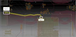
This illustration reveals two defined HFSS regions in a PCB design.
“Using HFSS regions in SIwave enables engineers to define regions of a PCB,” explains Denis Soldo, director at ANSYS. “These regions can be very complex—for instance, via breakouts, connector breakouts, and even bond wires in a package. So, for anything that’s 3D in nature, users are able to define a region of interest.
“All necessary ports and boundaries are automatically created and assigned. The HFSS 3D finite-element-method (FEM) engine is then called upon to specifically solve for that region of interest. All the results are then automatically back-annotated into SIwave for a complete simulation.”
This hybrid solution is extremely beneficial—it essentially combines accuracy with fast results. Soldo adds, “We are basically combining two different engines: full 3D FEM for 3D regions and the method-of-moments (MoM) transmission line solver in SIwave for simulating long transmission lines. In today’s world, you can think of a typical server board with 30 to 40 layers with frequencies of interest ranging from 10 to 20 GHz. This is going to be an extremely large problem electrically—you’re talking about thousands of wavelengths. Simulating this with even a supercomputer could take days or weeks. By combining SIwave and HFSS, we basically provide engineers with the best of both worlds. The result is fast and extremely accurate simulation results.”
Thanks to advances made by ANSYS, a much more automated process can be achieved versus typical methods utilized in the past. “In the past, engineers would use a ‘divide-and-conquer approach,’ which is very manual in nature,” says Soldo. “Of course, they would identify regions of interest. You could have a differential via pair and manually cut it out. This would be simulated to obtain results—usually in a touchstone format. Then you’d run a transmission line solver or a circuit solver for a signal net. You’d also include a connector-breakout region, run another 3D simulation, etc.
“In the end, you would end up with three, four, or five different data sets. Then, you would manually stick all of this together in a circuit simulator and run a transient simulation to look at the overall transient performance. This is a typical ‘divide-and-conquer’ approach. Now, that’s all fully automated in SIwave with automatic region assignments and HFSS being called in the background.”
ANSYS has performed extensive analysis to determine the effectiveness of this hybrid approach at higher frequencies. Soldo adds, “We have done extensive internal testing and data comparisons between SIwave-only simulations and this enhanced approach that involves SIwave combined with HFSS regions. Up to 8 GHz, we have observed that there’s not much of a difference in the results. However, at higher data rates and higher frequencies (i.e., above 10 GHz), we have observed the difference in the results. Those via transitions and connector breakouts make an impact at higher frequencies—and this is why 3D accuracy is definitely required for these types of simulations.”

