Dive into LNA Design
A low-noise amplifier (LNA) is a critical component in a receiver design, as its performance heavily determines the receiver’s overall performance. Those involved with designing LNAs must ensure that noise figure is minimized while also being mindful of other parameters. In the application note, “Design of a 10 GHz Low-Noise Amplifier,” National Instruments presents the design of an LNA that operates over a frequency range of 10.0 to 10.7 GHz. The NI AWR Design Environment is used to design and simulate the LNA.
The LNA is designed with the NE3515S02 heterojunction field-effect transistor (HJFET). At 10.4 GHz, this transistor has a minimum noise figure of approximately 0.3 dB along with roughly 12 dB of associated gain. Furthermore, a 12-mil-thick Rogers RO4003C laminate is used for the design.
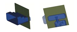
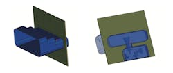
A waveguide-to-microstrip adapter is incorporated into the input section of the LNA. This adapter was simulated with the Analyst 3D electromagnetic (EM) simulator. The next step of the design process involves the planar structures, which are the amplifier stages and bandpass filter. The LNA consists of two amplifier stages, enabling it to achieve greater than 20 dB of gain. The bandpass filter is placed at the output of the second amplifier stage to reduce out-of-band gain.
Initially, the Microwave Office software was used to simulate and optimize the amplifier stages and bandpass filter via closed-form distributed transmission line models. Final adjustments and design verification were then achieved by using the AXIEM 3D planar EM simulator. The output transition is the final section of the overall RF design. This transition is realized with a coaxial connector that is placed perpendicular to the printed-circuit board (PCB).
The LNA’s enclosure is then described in detail. A specific cover is designed to prevent potential spurious oscillations. Lastly, 10 prototypes were assembled and measured. The measurements demonstrated good agreement with the simulated results, proving that the LNA has a gain of approximately 21 dB at 10.37 GHz. In addition, noise figure is below 0.6 dB across the entire 700-MHz band.
National Instruments Corp., 11500 N. Mopac Expwy., Austin, TX 78759-3504; (877) 388-1952

