MEMS Technology Fuels Timing Solutions
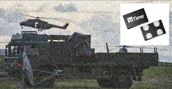
A line of precision timing solutions based on microelectromechanical-systems (MEMS) technology have been developed to handle harsh conditions in defense and aerospace systems. The frequency-reference sources—the Endura timing solutions from SiTime Corp.—can be specified for a number of different performance parameters, including operating frequency, frequency and phase stability, and power consumption, as needed for in-field and space systems with long-term timing requirements (see figure).
Based on MEMS technology, these frequency-reference sources can endure harsh shock and vibration conditions for reliable long-term military and aerospace systems.
“When exposed to high levels of shock, vibration, and extreme temperatures, legacy timing components have been prone to failure, degrading system performance and reliability,” says Piyush Sevalia, executive vice president of marketing. “To solve these problems, SiTime created an oscillator system of silicon MEMS, analog circuits, compensation algorithms, and advanced packaging, which is designed to outperform any other available timing solution in harsh environments. For example, Endura precision TCXOs deliver 4 parts per trillion per g (ppt/g) of acceleration sensitivity, which is 50 times better than legacy quartz-based solutions. With such performance, we believe that Endura will transform the oscillator landscape in aerospace and defense.”
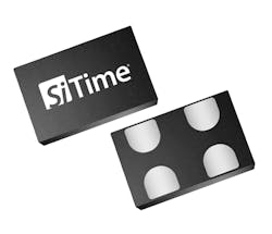
As an example, the Endura SiT8944 oscillator has an available frequency range of 1 to 110 MHz with low acceleration sensitivity of 0.1 ppb/g and an operating temperature range of −55 to +125°C. It’s designed for shock levels to 10,000 g’s and provides 70 g vibration resistance. The device fits within a compact 2.0- × 1.6-mm package and conforms to MIL-PRF-55310, MIL-STD-883, and AEC-Q100 specifications.

About the Author
Jack Browne
Technical Contributor
Jack Browne, Technical Contributor, has worked in technical publishing for over 30 years. He managed the content and production of three technical journals while at the American Institute of Physics, including Medical Physics and the Journal of Vacuum Science & Technology. He has been a Publisher and Editor for Penton Media, started the firm’s Wireless Symposium & Exhibition trade show in 1993, and currently serves as Technical Contributor for that company's Microwaves & RF magazine. Browne, who holds a BS in Mathematics from City College of New York and BA degrees in English and Philosophy from Fordham University, is a member of the IEEE.
