Rotman Lens’ Electronic Beam Steering Aims At 5G Signals

Download this article as a .PDF
Mobile wireless communications is heading toward its fifth generation (5G) with about as much fanfare as ever afforded a new group of technologies. Much of the excitement is due to the growing desires of wireless communications users for receiving such information as instant video and larger data files without delay. The massive improvements of 5G over the legacy wireless communications system, 4G Long Term Evolution (LTE), promise to deliver all that wireless users want and more, even to the extent of reaching to millimeter-wave frequencies for additional bandwidth.
What may be the most ironic part of the big build-up to 5G is the fact that there are yet no established standards in terms of modulation schemes, frequencies, and bandwidths. But one thing is for certain: Bandwidth will be needed, and millimeter-wave frequencies do not (as of yet) suffer the congestion of the many wireless applications found at lower frequencies. Millimeter-wave frequencies used in 5G and key components, such as antennas, will be needed for those high-frequency communications links. One promising solution for the antennas in those millimeter-wave links is the Rotman lens.
Precisely which millimeter-wave frequencies and bands will be used for 5G networks is not known as of yet, but different component and systems manufacturers are promoting the use of different frequencies; these include 28, 50, 77, and even 102 GHz. Components and subsystems at these frequencies have long been used in military applications for secure short-range line-of-sight communications links and for radar systems. More recently, they have been adopted by commercial vehicle manufacturers for collision-avoidance radars in automotive safety systems. For 5G wireless networks, which will combine nodes from satellite communications (satcom) systems and terrestrial, cellular base stations, users will experience a seamless and integrated network.
For example, in a more densely populated area such as a city, a user will connect to the network by means of cell sites. Outside of the city—in suburbs or the countryside, where lower populations offer less justification for erection of cell sites—users can connect to the 5G network by means of satcom system. When entering a building within the city, the user may even gain network access through a Wi-Fi wireless connection. The user will not notice any of the hand-offs and will not have to log onto the network when hand-offs are made. Of course, to make 5G work this effectively new hardware will be needed at higher operating frequencies than employed in current 4G LTE networks.
Some 5G infrastructure developments may result from the following considerations:
- Several companies are planning to launch networks of low-earth-orbit satellites (LEOS) or mega-constellations of satellites. These satellites are likely to be at Ka-band frequencies to achieve large data throughput and operate with acceptable levels of atmospheric signal absorption. Each satellite will be “visible” to a mobile device for 10 to 15 minutes before the device must be switched over to an adjacent orbiting satellite. Many LEOS are needed to provide wide geographic and continuous coverage.
- For 5G, Wi-Fi is likely to be at 60 GHz where there is a high level of atmospheric absorption resulting in limited signal propagation distance. The 4-GHz bandwidths available at that frequency support data rates to 15 GB/s.
- Backhaul links are likely to be at E-band frequencies, which will support similar data rates at propagation distances to 15 km.
- Mobile communications units will rely on satcom, Wi-Fi, and terrestrial-based wireless network connections, with the main uncertainty having to do with the operating frequencies for the wireless network.
Making Waves
While the exact frequencies that will be used for 5G systems may not as of yet be known, it is clear that higher frequencies, in the millimeter-wave frequency range, will be used to deliver the large amounts of data at high transmission speeds that are the looming characteristics of 5G wireless communications networks. As communications frequencies increase, communications systems and their components must comply with the requirements. For example, smaller signal frequencies require the use of components designed for the smaller wavelengths of those higher frequencies and changes in the way that signals propagate. A 4G cellular telephone operating at 2.1 GHz will suffer considerably less atmospheric absorption of signal power that a 5G cellular telephone operating at 77 GHz.
As a result, many more access points or base stations will be needed for millimeter-wave systems than for microwave wireless systems, thousands compared to hundreds for a given application region. The signal beams are much narrower at the higher frequencies, so beam steering technology is essential for capturing as much of a wireless signal beam’s energy and its data as possible. The Rotman lens represents a special and inexpensive means of performing beam steering at millimeter-wave frequencies.
The Rotman lens, named after Walter Rotman, was developed by Rotman and R.F. Turner in 1965.1 The true time delay (TTD) was first designed for use in radar systems at relatively low frequencies (around 3 GHz), where it provides multiple-beam operation and the capability to simultaneously detect targets in different directions without moving the antenna system. The Rotman lens antenna is a key component in many radar and electronic-warfare (EW) systems for its unique beam-steering characteristics. A Rotman lens works by orchestrating reflections in a “lens” structure having phase shifts such that the direction of the output array transmission depends upon the input direction of the incoming beam. With careful design, gains of 10 to 15 dB are possible.
The Rotman lens features a number of input (or beam) ports, a lens cavity, and a number of output (or array) ports, which are each connected through “phase correction” lines to a radiating element in an antenna array (Fig. 1). When the lens is excited at one of the beam ports a tilted beam is radiated from the array. By switching between input ports, the radiated beam can be scanned through the lens’ field of view.
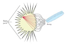
1. The operation of a Rotman lens is shown here. In receive mode, energy is focused on one of the beam ports, whereas in transmit mode, energy is directed in the array in the desired direction by feeding the signal into the appropriate beam port.
To achieve a high angular resolution between beams, a large number of beam ports are required. This can lead to a requirement for a high component count on the input side of the lens, as well as high spill-over losses due to small port widths (spill-over loss occurs when some of the signal being transmitted between the lens beam and array ports is incident on the sidewalls of the lens which are lined with absorber or dummy ports to prevent internal reflections; this causes a loss of signal power). The Arralis design includes a method of improving the angular resolution of a Rotman lens beamforming network while reducing the component count and system losses, without causing any significant change to the overall size.
The geometry of a conventional Rotman lens is shown in Fig. 2. A number of input (beam) ports are situated along a focal arc at one edge of the parallel plate region, with a number of output (array) ports located on the opposite edge. The array ports are connected to an array of radiating elements (or antennas) through phase correction lines of unequal length. When the lens is excited at one of the beam ports, a signal propagates through the parallel plate region, is sampled by the array ports, and transmitted via the phase correction lines to the array elements which radiate the signal into free space.
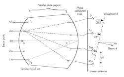
2. This diagram illustrates the multiple ports and the essential operating parameters of a Rotman lens.
The propagation path lengths from the beam port under excitation to the antenna elements provide a progressive linear time delay across the array. Due to constructive interference, a delay of Δτ between adjacent elements, separated by a distance of N, produces a radiation pattern at a scan angle, θs, relative to the central axis.
θs = sin−1[(c/N)Δτ]
where c is the speed of light in free space (Fig. 2). The lens is a true time-delay beam-forming mechanism: The values of c and N are constant and the beam scan angle depends only on the time delay, Δτ. Providing that Δτ is independent of frequency [as in transverse-electromagnetic (TEM) transmission media] or has only a weak dependency (as in so-called quasi-TEM transmission media such as microstrip), the scan angle does not vary with frequency, as is the case with phased-array antennas. The lens features three focal points, F1, G, and F2, which, when excited, form radiation patterns with peaks at −αº, 0º, and +αº, respectively. The capabilities of Rotman lenses are well known to many users in the field.
Retrodirective Operation
A Rotman lens is an ideal retrodirective antenna for a 5G system (Fig. 3). When a signal is received from one direction, it can automatically be transmitted back in the same direction without movement of the lens or complicated circuitry; in addition, the response is instant. As an example, imagine a Wi-Fi wireless access point in the corner of a room that receives a transmission from an angle of 30 deg.: t can immediately properly align and transmit back in the same direction.2-4
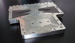
3. The precision machining required in the waveguide structure can be seen in this 94-GHz Rotman lens, which measures only 7 cm long. (Courtesy of Arralis Ltd.)
Another example is following a low-earth-orbit (LEO) satellite as it moves across the sky in a period of 10 to 15 min. The connected device on the ground can “lock-on” and stay with the satellite throughout this period. Even more significant is the fact that if the receive antenna is located on a vehicle which is moving and turning, it will constantly maintain alignment with the LEO satellite. When a new satellite appears on the horizon, the signal is automatically acquired again, without noticeable time delay (Fig. 4).
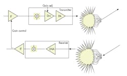
4. This basic block diagram shows one channel of a retrodirective system layout using Rotman lenses.
At millimeter-wave frequencies, the lens is best constructed in a waveguide structure to avoid circuit substrate losses. This also requires very careful and precision machining; in particular, the array waveguide paths must be phase matched or the effect upon the phase array will be high sidelobes or poor directivity. The “spillover” areas, as mentioned earlier, either must be absorbed—lined with an RF absorbing material—or, as is common at microwave frequencies, terminated at 50 Ω. Another great advantage of the Rotman lens is that its topology is essentially flat, making it ideal for integration in vehicles and aircraft.
Military organizations such as the U.S. Army Research Laboratories (ARL) have expressed great interest in Rotman lenses for their capability to serve multiple functions, such as radar and communications systems, with a single antenna. In fact, the ARL is currently pursuing key technologies for the integration of low-cost communications and radar systems, so as to create a single system and antenna that is capable of performing multiple functions. The functions will include target acquisition, combat identification, weapons guidance, secure point-to-point communications, and signal interception.
The Rotman lens is a suitable solution for such futuristic, multiple-function military systems. At the same time, the novel antenna is also ideal to meet the needs of the millimeter-wave portions of 5G wireless communications networks, with their high data rates and signal sources on the ground and in the air. It is clear from the performance needs of 5G systems that they will rely heavily on wireless interconnections with LEO satellites, cellular earth stations, and Wi-Fi “hotspots.” The Rotman lens is an ideal antenna for sending and receiving signals from those source, whether it is integrated as part of a fixed or mobile 5G wireless communications system.
Mike Gleaves, Chief Technology Officer
Arralis Ltd., Tierney Building UL, Castletroy, Limerick, Ireland; (353) (0) 61-748-264
References
- W. Rotman and R.F. Turner, “Wide-Angle Microwave Lens for Line Source Applications,” IEEE Transactions on Antennas and Propagation, Vol. 11, No. 6, 1963, pp. 623-632.
- S. Christie, R. Cahill, N. B. Buchanan, V.F. Fusco, N. Mitchell, Y.V. Munro, and G. Maxwell-Cox, “Rotman Lens-Based Retrodirective Array,” IEEE Transactions on Antennas and Propagation, Vol. 60, No. 3, 2012, pp. 1,343-1,351.
- S. Christie, R. Cahill, N. Mitchell, Y. Munro, and A. Manabe, “Liquid crystal based Rotman lens antenna with switchable monopulse patterns,” Microwave and Optical Technology Letters, Vol. 55, No. 11, 2013, pp. 2,721-2,726.
- Cheng-Xiang Wang, et al., Heriot-Watt University, “Cellular Architecture and Key Technologies for 5G Wireless Communication Networks,” IEEE Communications Magazine, February 2014.

