A Primer on Circulators and Isolators
Download this article in .PDF format
This file type includes high resolution graphics and schematics when applicable.
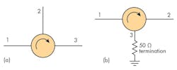
Circulators and isolators are three-port passive electronic devices that help direct the flow of microwave signals in RF equipment and systems. A port is defined as a connection point for either an input signal, output signal, or termination. Figure 1a shows the standard schematic symbol for a circulator. The arrow indicates the unidirectional flow any signals from port to port.
How a Circulator Works
Figure 1a shows a circulator, where any port can be an input or an output. A signal applied to port 1 will be passed to port 2 with minimum attenuation. A signal input to port 2 will pass to port 3, but not back to port 1. An input to port 3 will pass to port 1, but not in reverse to port 2. The amount of insertion loss from port to port is typically in the 0.2- to 0.75-dB range.
If one of the ports is terminated in a resistance equal to the impedance of the port, usually 50 Ω, the circulator becomes an isolator (Fig. 1b). An input signal at port 1 will pass to and exit port 2 if port 2 is properly matched to 50 Ω. If there is a mismatch at port 2, any reflected signal will be passed to port 3 and absorbed by the load. This protects or isolates port 1 from port 2 in the reverse direction.
Construction
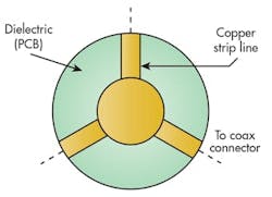
A circulator is typically a Y-shaped section of microstrip or stripline transmission line on a printed circuit board or other dielectric (Fig. 2). The line impedance is 50 Ω. The ports, spaced 120 deg. apart, are commonly terminated with SMA or N-type coaxial connectors.
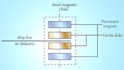
The Y-junction assembly is then sandwiched between two layers of ferrite material (Fig. 3). Two strong permanent magnets are positioned on either side of the ferrite disks. The magnets send a strong magnetic field axially through the ferrite disks. The ferrite material supports and focuses the magnetic field around the Y-junction. The axial magnetic field is called the bias.
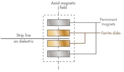
When a signal is applied to one of the ports, an electromagnetic field is set up in the strip line. This field then interacts with the applied bias magnetic field, causing the signal to rotate in one direction to the next adjacent port.
The assembly made up of the Y-junction and the ferrite disks forms a dielectric resonator that has a resonant frequency. The circulator is not operated at this frequency. Operation takes place in regions above or below the resonant frequency of the device, where attenuation is minimal.
Common Circulator Applications
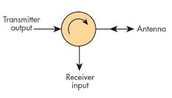
The most common application of a circulator is as a duplexer. A duplexer allows the transmitter and receiver in a radio or radar unit to share a common antenna (Fig. 4). The transmitter output is applied to port 1 and will pass to port 2, where the antenna is connected. The receiver input is connected to port 3. A signal received by the antenna is passed to port 3, but not back to port 1. The transmitter output is not passed to the receiver input. The key effect is to prevent the typically high transmitter power from damaging the receiver input circuits.
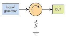
A common use of an isolator is shown in Fig. 5. The isolator is connected between a signal generator and some device under test (DUT). If all impedances are matched, the signal passes freely to the DUT. If there is a mismatch at the DUT or if the DUT is disconnected, it creates a high-voltage standing wave ratio (VSWR), causing a large reflected signal. The circulator absorbs this signal, protecting the usually expensive signal generator.
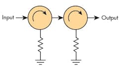
The attenuation of an isolator in the reverse direction is typically in the 20-dB range. If greater attenuation is needed, two isolators can be cascaded as shown in Fig. 6. The result is a four-port device that can boost attenuation to about 40 dB or so. Such four-port units are available as a single product rather than two individual isolators.
Specifications for Circulators and Isolators
When specifying or buying a circulator or isolator, the most important characteristics to consider are:
Frequency of operation and bandwidth: Circulators and isolators can operate over a range from about 700 MHz to 20 GHz. Special designs may permit operational frequencies as low as about 50 MHz and as high as 100 GHz. Most devices available have a narrower operating range with a finite bandwidth. When operating above resonance, lower frequencies are better accommodated over narrower bandwidths. Below resonance operation usually allows for wider bandwidths.
Insertion loss: This is the attenuation from port to port in the forward direction. It usually ranges from 0.1 to 0.75 dB.
Isolation: This is the attenuation in the reverse flow direction. It is typically in the 17- to 35-dB range.
Power: This is the average maximum power that the device can handle. Forward and reverse (reflected) power levels are usually given. Typical power ratings range from 1 to 1,000 W.
Temperature range: This is important as ferrite characteristics and magnetic field strengths vary with temperature. A common maximum range is –50 to +100°C.
Impedance: The characteristic impedance of the ports is virtually always 50 Ω.
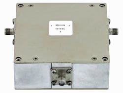
Figure 7 shows a representative commercial circulator.
References
1. Cheung, W.S. and Levien, F.H., Microwaves Made Simple, Artech House, Inc. 1985.
2. Edridge, Tony, Basic Facts about Circulators & Isolators, M2 Global Technologies, Ltd.
3. Frenzel, Louis E., Principles of Electronic Communications Systems, 4th edition, McGraw Hill, 2016.
4. MECA Electronics, Inc., Isolator & Circulator Basics, Microwave Product Digest, June, 2010.
5. Spectrum Elektrotechnik. GmbH, Isolators & Circulators.
Download this article in .PDF format
This file type includes high resolution graphics and schematics when applicable.

