Delivering Higher Power Density and Low Noise for New Space Apps
What you’ll learn:
- What is the factorized power architecture (FPA)?
- Developing a “New Space” FPA power-delivery network.
- How to meet radiation-tolerance parameters.
To reduce expensive communication traffic between satellites and the Earth, satellite platforms are hosting a greater amount of processing power. Thus, meeting the demands of more onboard computation and signal- and data-processing hardware means an increase in system power and point-of-load (PoL) requirements. Because hard-switched converters have drawbacks in size, efficiency, and electromagnetic interference, system engineers and power-supply designers are driven to consider more advanced power-supply topologies.
Due to the physical size of modern ASICs, FPGAs, CPUs, and GPUs—and their necessary cooling solutions—circuit-board real estate around these big chips is precious. These chips require progressively lower voltages with increasing currents; hence, the need for an optimized power-delivery network (PDN).
Therefore, it’s helpful to divide the PDN task into two sections: a regulation section that can be placed in a convenient location, and a power-delivery section that benefits from being placed as close to the load as possible. This is a fundamental principle of the factorized power architecture (FPA) described below.
Soft-switching topologies hold distinct advantages over hard-switched converters by enabling high fundamental conversion frequencies with low harmonic noise. Compared to a hard-switched, multi-phase topology:
- A zero-voltage switching (ZVS) and zero-current switching (ZCS) topology, running at the highest practical frequency, is more space-efficient and wastes less power.
- A ZVS and ZCS topology doesn’t have the high-frequency, harmonic-series noise profile character.
- Converters with a >1-MHz operating frequency don’t have troublesome 100- to 500-kHz frequency content.
- Low harmonic content and a high fundamental conversion frequency means a compact noise-filter implementation.
Power modules operating at >1 MHz help engineers create low common- and differential-mode (CM and DM) noise designs, particularly when component arrangements and device interconnects are properly considered.
As always, input and output filters are required and must be designed and placed properly. However, the inherent nature of high-frequency, soft-switching converters makes this task easier.
Factorized Power: Delivering High Current and Low Voltage Efficiently
The top challenges for satellite power-system designers include:
- Higher and higher load-current requirements, from tens to hundreds of amps.
- Loads requiring faster transient response with tighter tolerance windows.
- Requirements for lower PDN losses and impedances.
- Expanding use of higher-voltage buses to reduce conductor sizes.
In addition to the advancing electrical requirements in space, radiation total ionizing dose (TID) and single-event effects (SEE) requirements enter the mix. In some cases, the "New Space" philosophy of smaller, faster, and less-costly space platforms and launches led to the adoption of rad-tolerant design methods as a cost-reduced substitute for radiation hardening.
This new approach is based on determining an acceptable level of performance and reliability based on the specific mission, then developing boards and electronics based on size, weight, and power consumption (SWaP) tradeoffs, as well as cost-effectiveness. This design strategy suits low-Earth-orbit (LEO) and medium-Earth-orbit (MEO) satellites inside the Van Allen radiation belt.
To create a high-current, high-density PDN, consider using a factorized power architecture. For example, Vicor's New Space FPA divides the PDN into three stages. The first stage is a fixed-ratio (divide by 3), isolated and unregulated module called a bus converter module (BCM). The next stage is a pre-regulator module (PRM) that provides voltage regulation as the input voltage and output load changes. The final stage is a fixed-ratio voltage transformation module (VTM) to create the low voltage required by the load.
In the current generation of Vicor New Space converters, an unregulated first-stage BCM provides isolation from the spacecraft bus, a supply voltage for the downstream converters, and voltage transformation to create an intermediate bus voltage compatible with the downstream converters. The current BCM design offers a 3:1 transformation ratio to convert 100 VDC to 33 VDC, but other transform ratios are being studied and considered to support other bus voltages.
The second-stage PRM performs accurate output-voltage regulation with a trimmable output-voltage range of 13.4 V to 35 V.
The third-stage VTM involves power delivery. It transforms the higher voltage from the PRM to the voltage required by the load. Currently, there are two transformation ratios: 8:1 and 32:1. VTMs are called current multipliers because the input-to-output current transformation is the inverse of the voltage transformation ratio. As an example, 6 A injected into the 8:1 VTM results in a 48-A output current.
Designing a Low-Noise FPA for New Space
BCMs, PRMs, and VTMs are the components that make FPA possible. The current generation of radiation-tolerant New Space BCMs, using Vicor's Sine Amplitude Conversion (SAC) topology, has an impressive peak efficiency of 96.9%.
Vicor PRMs use the company's ZVS buck-boost regulator control architecture to give high-efficiency step-up and step-down voltage regulation and soft-start. Maximum efficiency is achieved when VIN ≈ VOUT, with 97% peak being achieved with the latest PRMs.
High-efficiency VTM current multipliers use a proprietary ZCS/ZVS Sine Amplitude Converter, which transforms a nearly pure sinusoidal waveform with high spectral purity and common-mode symmetry. These characteristics mean it doesn’t generate the harmonic content of a typical hard-switched pulse-width-modulation (PWM)-type converter and generates minimal noise.
The control architecture locks the operating frequency to the powertrain's resonant frequency, enabling up to 97% efficiency and minimizing output impedance by effectively canceling reactive components. Such very low, non-inductive output impedance allows it to respond almost instantaneously to step changes in the load current (see figure).
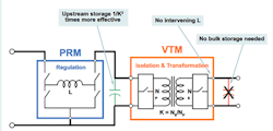
The VTM responds to load changes regardless of magnitude in less than a microsecond. The VTM’s high bandwidth obsoletes the need for large point-of-load capacitance. Even without external output capacitors, the output of a VTM exhibits a limited voltage perturbation in response to a sudden power surge. A minimal amount of external bypass capacitance (in the form of low equivalent-series-resistance/equivalent-series-inductance (ESR/ESL) ceramic capacitors) minimizes the output transient voltage overshoot.
Because the VTMs are nearly transparent without capacitive or inductive storage, bulk capacitance can be placed on the input voltage side—taking advantage of the squared voltage term along with the linear voltage transform ratio:
Ej = 1/2 x CV2
where Ej = stored energy in joules, C = capacitance in farads, and V = voltage in volts.
As an example, for equivalent energy storage with the Vicor VTM that has an 8:1 transform ratio, 25 µF of input capacitance at 28 V acts very much like 1600 µF of output capacitance at 3.3 V (see figure, again).
Because the VTMs are nearly transparent, the capacitance transfer ratio between input and output can help with pulsed loads. This transform means smaller values of capacitance (at the higher voltage) can be used to serve pulse-load requirements.
Vicor's radiation-tolerant New Space VTMs have peak efficiencies of 94.7% for 8:1 transformation (3.3 V at 50 A) and 92.9% for higher-current 32:1 transformation with capability of 0.8 V at 150 A.
Benefits of FPA
The factorized power architecture enables power-system density and high-current demands to keep pace with rapidly advancing CPU, GPU, and ASIC technologies. Some key system design advantages include:
- Reduced PDN real-estate consumption near the CPU/GPU by 50% or more.
- An order-of-magnitude reduction in PDN and associated board losses.
- Unfettered performance by placing the PRM in non-critical board edge areas.
- Simplified CPU I/O routing.
- Mitigated risk of placement near the processor’s SerDes because of lower noise performance of the VTM
Overall peak efficiency for a power system—including the combination of a BCM, PRM, and VTM—operating from an unregulated dc source and supplying a regulated, low-voltage dc output is 89% (for 100 V:3.4 V at 50-A transformation) and 87.3% (for 100 V:0.8 V at 150-A transformation). With higher efficiency comes lower total heat dissipation, an important consideration in a power system design for spacecraft where cooling mechanisms require additional mass and structure.
A Summary of Radiation-Tolerance Parameters for the Vicor New Space FPA
Lots of work is required to create power modules that will survive useful periods in low and medium Earth orbits:
- To meet TID requirements, components must be carefully selected and screened for radiation performance; parameter variations are included in worst-case analysis to assure performance.
- To meet enhanced low-dose-rate sensitivity (ELDRS) requirements, only known-ELDRS-performance-rated components are used, or the parts are tested at low-dose rates.
- To meet single-event performance requirements, one must perform extensive testing with accelerated charged particles. All selected parts are tested and analyzed to survive up to a linear energy transfer of 35MeV-cm2/mg. To mitigate for single-event functional interrupts (SEFIs), one should implement dual-redundant internal powertrains with monitoring and power-cycling capability.
Vicor New Space radiation-tolerant power modules are survival-rated at 35MeV-cm2/mg and TID rated at 50 krad. Worst-case circuit analysis (WCCA) was performed on all circuits, including statistical confidence limits (90% confidence with 99% probability) based on sample testing of the parts. Extreme value analysis (EVA), root-sums-squared (RSS), and Monte Carlo analysis methods were used where appropriate to evaluate the power-module designs to ensure all parts will perform as expected.
About the Author
Ken Coffman
Field Applications Engineer, New Space Initiative, Vicor Corp.
Ken Coffman is an engineer, writer and publisher in the Phoenix, AZ area with more than 20 years of experience designing and troubleshooting advanced power supplies. Currently, Ken is a Senior Field Applications Engineer assigned to Vicor Corp.’s New Space Initiative.
