DoD Cable and Connector Standards Simplified
Download this article in PDF format.
Standards are essential requirements for any industry seeking to eliminate the chaos that would ensue if manufacturers had no defined performance and construction guidelines to follow. For example, although RF and microwave cables, cable assemblies, and connectors aren’t the most complex devices, without standards there would be hundreds if not thousands of incompatible products, with no way to easily compare them. Yet, specifying these products in today’s robust market can still be very confusing, and the goal of this article is to provide basic information about U.S. Department of Defense (DoD) standards related to cables and connectors.
As the DoD has infamously demonstrated, it’s possible to have too much of a good thing when the burden posed by standards effectively creates the chaos they’re intended to eliminate. That is, while standards are essential, it was inevitable that they would grow like weeds until they became so unmanageable that it turned into enormous burden to anyone who had the temerity to use them.
How We Got Here
Led by the United States and France in the late 18th and 19th centuries, countries began to realize the benefits of having standards that defined the components, subsystems, and systems used in their military equipment. By World War II, virtually every country with even a modest military force had adopted them. Not surprisingly, these standards proliferated over the years, and by 1990, the DoD assessed that they numbered about 30,000, covering such obscure topics as specifications for the rubber used on swim fins.
Owing to the increasing outrage from military contractors and the sheer impossibility of maintaining them, Defense Secretary William J. Perry wrote in 1994 what has become known as the “Perry memo.” The memo effectively prohibited the use of most standards without a waiver and directed contractors to use suitable commercial off-the-shelf (COTS) products whenever possible in their place. The debate continues over how effective COTS has been in bridging the gap between commercial and military products, simplifying the process for contractors, and reducing costs.
An enormous number of DoD standards remain in place. In fact, the DoD has the most comprehensive requirements of any government agency in the world, and technological advances, market demands, and the emergence of new applications make it essential that these standards be revised, although it typically takes several years to release revisions to a standard.
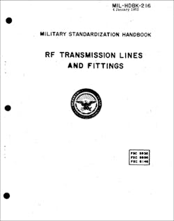
Perhaps the worst example of this is MIL-HDBK-216, a handbook that covers RF transmission lines and connectors that hasn’t been revised since 1962 (Fig. 1). It was, in fact, eliminated without replacement in 2001, but was subsequently resurrected after a 2016 study determined that such a massive task would be worth the effort. The Electronic Components Industry Association (ECIA) committee CE-2.2 is currently in the process of revising specifications for 50- and 75-Ω rigid coaxial transmission lines and connectors per EIA-RS-225A and EIA-RS-259A. When completed, it’s hoped that the result will serve as a useful guide for the selection and use of RF/microwave connectors and cables.
The Key Standards
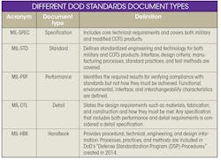
There are five entirely different types of documents used by the DoD today (see table). Not surprisingly, there are even standards defining how standards must be formatted and how their content must be presented. For MIL-SPECs, this is MIL-STD-961; for MIL-STDs, it is MIL-STD-962; and for handbooks, it is MIL-STD-967.
MIL-DTL-17
MIL-DTL-17 is the primary standard designers refer to when designing or specifying cables for military and aerospace applications. It details specifications for flexible and semi-rigid coaxial cables with solid and semisolid dielectric cores as well as single, dual, twin, and triaxial conductors.
The current version of MIL-DTL-17 is revision “J,” produced in 2014. This standard was formerly known as MIL-C-17, since it was developed in the 1940s and was revised many times over the years to better define the mechanical and electrical requirements for military coaxial cables. The “RG” nomenclature (e.g., RG-59) was replaced by M17 designations in the 1970s when the specification was renamed as MIL-DTL-17.
For 50-Ω cables, the most important changes were the addition of swept-frequency measurements for attenuation and return-loss requirements (voltage standing-wave ratio, or VSWR). Before they were added, attenuation requirements were only specified at three frequencies, which resulted in inaccurate measurements at other frequencies. So, the standard now specifies continuously sweeping maximum VSWR and attenuation from 50 MHz to 11 GHz with VSWR remaining at or below 1.15:1 at 100 MHz and 1.33:1 at 11 GHz.
Nor was there any requirement for adhesion of the dielectric core to the center conductor, with the result that it was possible to pull the center conductor out of the assembly when stripping it. Revision E provided criteria for remedying this while also requiring all cables be manufactured and tested to meet maximum shrink-back allowance between the dielectric core and the cable jacket. Other advances included a stress-crack resistance test on FEP (fluorinated ethylene propylene) and PFA (perfluoroalkoxy) jacketed cables, and the use of Type II PVC (polyvinyl chloride) for jackets, replacing the earlier specification for Type 1.
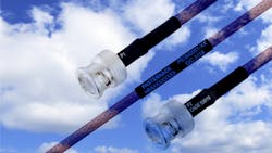
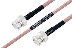
Coax cables meeting MIL-STL-17 have high thermal conductivity for excellent power-handling capability over broad temperature ranges and shielding effectiveness ranges from 40 to 60 dB, along with very low passive intermodulation distortion. With silver-plated outer conductors, oxidation is prevented, minimizing changes in attenuation over time. Many MIL-DTL-17 cables are rated to 1 GHz, some to 12.4 GHz, and an increasing number to 20 GHz (Fig. 2).
MIL-T-81490
Although this standard is designated for coaxial cables used in airborne platforms, it can also be an alternative to MIL-DTL-17, especially for higher frequencies. It’s a performance rather than a detail specification, so it gives cable manufacturers more flexibility in how they meet its requirements.
This is highly desirable for cables designed for use at high frequencies because of higher precision, materials, and other factors that must be considered in cables with very small diameters. The resulting product must still meet minimum performance requirements regardless of how the cable is constructed, with the caveat that these details can vary considerably among suppliers. Cables meeting MIL-T-91490 may, but not always, exceed meeting MIL-DTL-17.
The standard specifies flexible, semi-flexible, and rigid cables, and defines in which cases each one can be used, which are more or less self-explanatory and is typical of how cables are generally used. For example, flexible cables are specified for places where bending is required, such as in long lengths of cable. However, it also extends this to shock-mounted equipment, and places where field testing (for instance) can result in repeated flexing. Semi-flexible cables aren’t to be used in places where repeated bending or flexing occurs or in shock-mounted equipment. Finally, semi-rigid or rigid cables never bend once they’re formed when manufactured.
MIL-PRF-39012
This standard, which is dedicated to coaxial connectors, provides requirements and test methods for them when used with flexible and semi-rigid cables. It has two main classifications: Class 1 connectors cover those with the highest performance at defined frequencies, and Class 2 connectors that are intended to provide a mechanical connection within an RF circuit. The standard goes even further, classifying connectors for six different types:
- Class A: Field-serviceable types that don’t require special tools for assembly.
- Class B: Non-field replaceable types that don’t require special tools but are designed only for original installations.
- Class C: Field-replaceable connectors that require only standard military crimping cable stripping tools to assemble.
- Class D: Field-replaceable connectors for use with semi-rigid cables that require standard military crimp tools for the center contact and outer ferrule.
- Class E: Field-replaceable connectors for semi-rigid cables requiring standard stripping dimensions and military tools. Solder is the method required for assembly of the connector to the cable’s outer conductor.
- Class F: Field-replaceable connectors for semi-rigid cables requiring standard stripping dimensions and military assembly tools. These connectors are solderless.
In its latest versions, MIL-PRF-39012 added new qualification testing and approval requirements present in MIL-STD-790 (Established Reliability and High-Reliability Products) and made changes that increase the scope of the standard.
When in Doubt, Check the QPL
It’s important to note that while the standards described above are likely to be encountered by designers, they’re not the only ones, as the primary standards refer to many others (such as MIL-STD-202). Because MIL-DTL-17 cables are used in applications other than defense systems, they often include requirements contained in commercial standards such as those employed for use in designing automotive systems.
Moreover, the primary cable and connector standards themselves are divided into various categories, including testing materials, qualification, conformance testing and inspection, and electromagnetic compatibility (which has its own set of standards). What this means in practice is that few designers have the time (or interest) in deciphering all of these documents. They need a single source of information that lists manufacturers and products meeting all of the main requirements stated above, and likely even more.
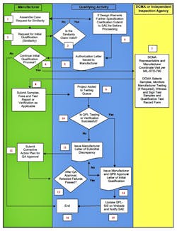
Fortunately, the DoD’s Qualified Manufacturer’s List (QML) and Qualified Product List (QPL) serve this purpose and represent the “gold standard” for selecting acceptable products. As usual, however, the QPL isn’t the easiest government resource to navigate, but it’s nevertheless far easier and more reassuring than any other method. The process for certification is daunting (Fig. 3).
What’s also important to remember is that even though a product may not be QPL-listed, it doesn’t necessarily mean that it falls short of meeting its requirements or is in some way inferior. There can be several reasons for this. For instance, the manufacturer may not have included a specific product on the QPL as it serves other applications beyond defense, has yet to get around to it, or a variety of other reasons. And if it’s a custom assembly, it can’t be QPL-listed in the time required for response to the solicitation.
In fact, DoD’s federal acquisitions policy document notes that if a company can demonstrate to the satisfaction of the contracting officer that its product meets QPL standards before the date specified for the award of a contract, it can’t be denied the opportunity to submit a proposal solely because the company’s product isn’t on the QPL.
That said, when a solicitation calls out that a specific component within the system must be QPL-listed, there’s the distinct possibility that the contracting officer may for whatever reason simply reject it. In addition, if a company is in direct competition for the award with a company whose same type of product is QPL-listed, the former is more likely to get the nod. In short, it’s always a gamble.
Connecting with the Future
Standards for cables and connectors have served the defense industry well for many years and there’s every reason to believe they will continue to do so. But new challenges lay ahead, one of the most important being the DoD’s increasing focus on higher frequencies due in part to the new threats from adversaries in spectral regions at or above 100 GHz.
Since the earliest days of RF and microwave connectors, the challenge for those defining them has been to provide the highest possible performance using the most advanced fabrication technology available at the time. Millimeter-wave frequencies take this to an entirely new level because the required coaxial connectors are incredibly tiny and fragile. Moreover, they’re potentially bumping up against the limits of the fabrication technologies employed to make them.
Since the 1960s, the IEEE’s P287 “Standard for Precision Coaxial Connectors (DC-110 GHz)” has been focused on the goal of creating standards for these components, and their efforts, along with those of the microwave and test-and-measurement industry, have delivered impressive results. The target in the future will be attempting to ruggedize these connectors for defense applications, which are obviously far more demanding than relatively benign benchtop environments.
Accomplishing that won’t be simple, however, because although 0.8-mm connectors are currently in production for test-and-measurement platforms, research is underway concerning 0.6-mm and even 0.4-mm connectors designed to serve systems operating at hundreds of gigahertz. Regardless, there won’t be any shortage of problems to solve for cable and connector manufacturers in the future, as well as for the organizations charged with the responsibility of creating standards for them.
Peter McNeil is a Marketing Manager at Pasternack.
About the Author
Peter McNeil
Marketing Manager, Pasternack
Peter McNeil is a marketing manager at Pasternack and has over 25 years of experience in sales development, product management, and marketing in the telecommunications, RF, and microwave industries. He currently oversees the development and delivery of several of Infinite Electronics brands content, including Pasternack.
