Linear-in-dB RMS Power Detector Spans 100 MHz to 70 GHz

This article appeared in Electronic Design and has been published here with permission.
The RF signal chain is defined by power rather than voltage or current. Providing root-mean-square (RMS) measurement of this power over a wide dynamic range is critical circuit and system requirement. Fortunately, today’s ICs feature frequency range and performance capabilities that continue to extend to meet the needs of the ever-growing electromagnetic spectrum of interest.
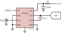
Among the latest offerings is the LTC5597 RMS Power Detector from Analog Devices. As with so many tightly focused RF parts, it implements one primary function and does it well. This 8-lead device in a diminutive 2- × 2-mm package (Fig. 1) boasts a fully specified operating span of 100 MHz to 70 GHz with a 35-db “linear” dynamic range. Its 28.5-mV/dB logarithmic slope has a typical error of less than ±1 dB. Among its other specifications are ±2-dB flat response from 100 MHz to 60 GHz.
The device is well-suited for measurement of waveforms with crest factor (CF) as high as 12 dB, including waveforms that exhibit a significant variation of the crest factor during measurement—an increasingly frequent scenario in today’s advanced-modulation environments. Such specifications and performance make it a good option for a wide range of applications, including but not limited to point-to-point microwave links, satellite communication links, instrumentation and measurement equipment, military radios, 5G/LTE/Wi-Fi wireless networks, RMS power measurement, and transmit power/receive gain control.
The averaging bandwidth can be externally adjusted using a capacitor to achieve higher accuracy along with lower output ripple. The 3.3 V draws just 33 mA (typical) while an enable pin switches the device between active-measurement mode and a low power shutdown mode.
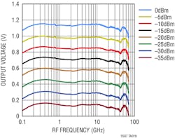
As with most RF parts, designers prefer an abundance of charts and graphs on the datasheet. The comprehensive 22-page datasheet includes over two dozen graphs (Figure 2 is one example) plus tables showing performance, errors, and deviations across a wide array of factors including voltage, input power, temperature, and more.
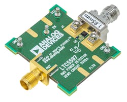
Designs also welcome (and expect) evaluation boards for these devices, even though their basic interconnection schematic is quite simple. The DC2932A ($600) provides a PCB layout that employs the recommended microstrip transmission-line structure and endpoint transitions (Fig. 3). (Note that the input impedance to LTC5597 is internally matched to 50 Ω.) Support for the demonstration circuit includes schematic, design, and integration files, and a user guide.
About the Author

Bill Schweber
Contributing Editor
Bill Schweber is an electronics engineer who has written three textbooks on electronic communications systems, as well as hundreds of technical articles, opinion columns, and product features. In past roles, he worked as a technical website manager for multiple topic-specific sites for EE Times, as well as both the Executive Editor and Analog Editor at EDN.
At Analog Devices Inc., Bill was in marketing communications (public relations). As a result, he has been on both sides of the technical PR function, presenting company products, stories, and messages to the media and also as the recipient of these.
Prior to the MarCom role at Analog, Bill was associate editor of their respected technical journal and worked in their product marketing and applications engineering groups. Before those roles, he was at Instron Corp., doing hands-on analog- and power-circuit design and systems integration for materials-testing machine controls.
Bill has an MSEE (Univ. of Mass) and BSEE (Columbia Univ.), is a Registered Professional Engineer, and holds an Advanced Class amateur radio license. He has also planned, written, and presented online courses on a variety of engineering topics, including MOSFET basics, ADC selection, and driving LEDs.
