MIPI A-PHY: A Resilient Asymmetric Data Transport for a Vehicle’s Lifespan

This article appeared in Electronic Design and has been published here with permission.
Download this article in PDF format.
What you’ll learn:
- The impact of EMI, noise, and increased symbol rates on in-vehicle architectures.
- The mechanisms that drive the MIPI A-PHY v1.0 interface.
- Comparing A-PHY’s PAMx/JITC/RTS solution with a PAMx/FEC implementation.
In September 2020, the MIPI Alliance announced the release of its new A-PHY specification, the first industry-standard, long-reach, serializer-deserializer (SerDes) physical-layer (PHY) interface. MIPI A-PHY v1.0 serves as the foundation of an end-to-end system designed to simplify the integration of cameras, sensors, and displays across a vehicle.
The specification provides a robust, multi-gigabit asymmetric data link, providing high-speed unidirectional data, embedded bidirectional control data, and optional power delivery over a single cable. MIPI A-PHY offers a near-zero packet-error rate (PER) of 10-19 for unprecedented performance over the vehicle lifetime, ultra-high immunity to electromagnetic-interference (EMI) effects in demanding automotive conditions, cable reach up to 15 meters, and data rates as high as 16 Gb/s with a roadmap to 48 Gb/s and beyond.
In this article, we will analyze the complex automotive noise environment—in particular, its unique characteristics when compared with conventional non-automotive communication links. Our analysis shows that specific mechanisms for noise cancellation and error correction that target the negative effects of automotive EMI are needed to ensure safe and resilient operation of high-throughput data links over the vehicle’s lifespan. We will detail the mechanisms that were incorporated into A-PHY to ensure the integrity of data links over the vehicle’s lifetime.
Challenges for Automotive Multi-Gigabit Links
Electrical/electronic (E/E) in-vehicle architectures are undergoing a radical transformation to meet the needs of emerging use cases and system requirements, as well as to overcome the challenges that they present. Here are a few examples:
- High-quality, multi-sensor fusion requires long, high-throughput, safety-critical links between electronic control units (ECUs) and multiple sensors at the edges of the vehicle.
- High-quality displays require high-throughput links to multiple vehicle displays to ensure best-in-class user experiences.
- Harsh in-vehicle environments present significant challenges to multi-gigabit communication technologies, which require shielded cables to tolerate high EMI levels.
- Increasing data rates are pushing conventional automotive communication technologies to their limits, and they can no longer provide the required immunity margins to guarantee safe vehicle lifespan operation over shielded cables.
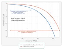
The significant increase in symbol rates needed to support higher bandwidths requires PHY interface operation at much higher in-band frequencies, which in turn imposes—or creates—limitations on the transmission. Factors such as decreased in-band transmitter power density to meet emission limits, decreased signal power at the receiver due to increased channel attenuation (Fig. 1), and decreased cable-shielding effectiveness (Fig. 2) leading to more noise coupling into the signal, all result in a significant degradation of signal-to-noise ratio (SNR) at the receiver.
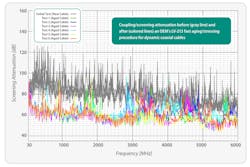
To further complicate matters, cable-shielding degradation gets worse with cable aging and flexing. Figure 2 shows how repetitive flexing of a coaxial cable results in a 25- to 30-dB decrease in screening attenuation at higher frequencies. That means the cable characteristics can change significantly over the lifetime of the vehicle—and, if not addressed by the PHY, the attenuation could have a direct impact on the resilience of the link over time.
Automotive Noise Environment
Having determined that the receiver on the link suffers from an impaired SNR when running at higher symbol rates, it’s also important to consider the noisy automotive environment. The vehicle is exposed to many electromagnetic noise components, the main elements in this environment being:
- Narrowband interference (NBI): Continuous narrowband noise, comprising a single or few contributions from a large external-to-the-vehicle transmitter(s). These noise components have bounded peaks and are very likely to be an issue. Standard electromagnetic-compatibility (EMC) tests, such as bulk current injection and RF ingress, test the receiver’s immunity to such noises.
- Transients on line (ToL): Large electrical transients with short duration (up to ~200 ns) but with very high amplitude.
- Alien crosstalk noise (Xtalk): Continuous broadband noise caused by neighboring aggressors in the cable harness and on-PCB traces.
- Vehicle-environment additive white Gaussian noise (AWGN): Continuous broadband environment noise comprising contributions from multiple independent sources, normally distributed with unbounded noise peaks but with low probability of occurrence.
As shown in Figure 2, the screening attenuation (SA) of “new” shielded cables can be 20 to 30 dB better than their worst-case SA, because SA degrades with in-car installation and during the vehicle’s lifespan due to cable aging and stressing. Based on a study of this phenomena, MIPI Alliance determined that A-PHY shall offer immunity to at least 40-mV-peak NBI coupled on the receiver’s pads. By comparison, other standards assume a maximum of ~6-mV peak NBI, though recent work suggests that immunity to much larger NBI peaks is required (90 dBµV RMS above 30 MHz, while MIPI’s 40-mV peak equals 89 dBµV RMS).
As less in-band signal power reaches the receiver, its equalizer needs to amplify more of the incoming signal to reconstruct the original transmit levels’ separation at its slicer, which is where decisions are made about the signal level. Certain elements in the receiver amplify both the data signal and its coupled noise, while a decision-feedback equalizer (DFE) improves the reconstruction of the original transmit levels without noise amplification.
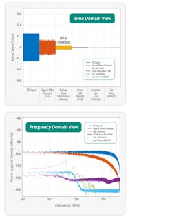
The following diagrams illustrate the different noise sources described above, with the dark blue representing the transmit signal and the orange representing the signal after channel loss. Figure 3 shows time- and frequency-domain plots of a system transmitting at a symbol rate of 4 Gbaud at 500 mV p-p over a channel with ~20-dB attenuation at its 2-GHz Nyquist frequency.
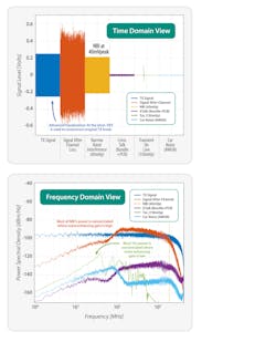
It’s also important to examine the receiver to see how these signals look at the slicer—that is, after the addition of the analog front-end and feed-forward equalizer (FFE) gains (Fig. 4). Even when we use a relatively advanced equalization and filtering that affords only ~15-dB amplification of the noise, we can see the large impact of the NBI relative to the desired reconstructed transmit levels. As seen in the frequency domain, it’s due to most of the NBI power is concentrated at a frequency where the noise-enhancing gain in the equalizer is high. By comparison, ToL noise occurs at a lower frequency that experiences much lower noise-enhancing gain.
The conclusion from this analysis is that high-throughput automotive links are EMI-limited and not AWGN-limited, as are conventional long-distance, non-automotive communication links. Thus, we need specific mechanisms for noise cancellation and error correction that target the negative effects of automotive EMI to ensure safe and resilient operation of high-throughput data links over the vehicle’s lifespan.
Enter MIPI A-PHY
MIPI A-PHY v1.0 is an asymmetric, high-throughput, resilient automotive interface that employs dynamic pulse-amplitude modulation (PAM), just-in-time NBI cancellers (JITC), and PHY-level retransmission (RTS) mechanisms for its higher-speed gears to ensure maximum link robustness:
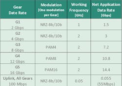
- PAM: A-PHY uses different modulation schemes for each speed gear, ranging from NRZ-8b/10b up to PAM16. In speed gears 3, 4, and 5, subset modulation (using lower-order modulation) protects packet headers, important data types, and retransmitted packets (Table 1).
- JITCs: The built-in noise cancellers provide more than 36 dB of just-in-time NBI cancellation.
- RTS: Dynamically modulated local retransmission provides a post-RTS PER of <10-19. This translates to a mean time between packet errors of more than 10,000 years, even with a link operating at 100 Gb/s.
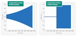
The scale of the challenges resolved by A-PHY also plays out in the type of noise profiles present in the vehicle. Noise attacks can be either gradual or instant (Fig. 5), and the ISO standard for EMC testing allows for both types of attack profiles. More specifically, multiple constant wave and amplitude-modulation NBI attack profiles may be encountered and can be either gradual or instant, while pulse-modulation NBI and ToL attacks are, by definition, instant in their nature.
When NBI noise instantly attacks, some data packets are damaged before the JITC can converge and cancel the NBI. To overcome this, RTS is used to recover the data packets that were damaged before the JITC converged.
To hasten and ensure successful JITC convergence, we use a retraining sequence. For example, Figure 6 illustrates a 4-Gbaud PAM4, 40-mV-peak, 3-tone instant NBI attack, both with and without retraining of the JITC. As can be seen on the left side of the diagram, the four blue traces representing the slicer input at the receiver show clearly defined PAM4 levels until the noise attacks the signal. Just-in-time cancellation needs to occur while actual data is running on the link, and it’s clear from the destruction of the PAM4 signal that the noise cancellation is unable to converge to overcome the noise.
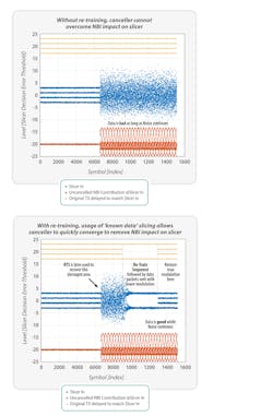
On the right side of the diagram, we see how the retraining process unfolds. The receiver requests the transmitter to transmit a retraining sequence comprising two-level known (predictable) data derived from the scrambler, which rapidly allows for JITC convergence and successful noise cancellation at the receiver—even while the noise continues. Following the convergence, PAM4 data is once again recognizable by the slicer. We then use RTS to retransmit the data packets that were damaged in the noise attack (not shown in the plot).
Comparison with Forward-Error-Based Systems
Table 2 shows a comparison of the in-vehicle noise handling of A-PHY’s PAMx/JITC/RTS solution versus that of a PAMx/FEC (forward error correction) implementation.
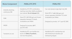
For PAMx/FEC solutions, the instant NBI, crosstalk, and AWGN noise components are all handled by the SNR gain provided by the FEC, which is approximately 6 dB. In other words, those three components all share the same 6-dB SNR gain budget targeting a post-FEC BER of 10-12, which is the equivalent of a PER that’s worse than 10-9 when using packets sized similarly to A-PHY’s maximum packet size.
For A-PHY PAMx/JITC/RTS solutions, the instant NBI is handled by the JITC/RTS mechanism combination, which provides more than 36 dB of noise cancellation. Crosstalk and AWGN noise components are handled by the SNR gain provided by the RTS, which is about 4 dB. These noise-handling mechanisms enable A-PHY to achieve a PER of 10-19.
In addition, when dealing with ToL noise components, the A-PHY RTS mechanism can manage error bursts of thousands of symbols, while practical FEC implementations are restricted by the degree of interleaving. This greatly limits the duration of the error bursts that FEC systems can handle.
Conclusion
As has been shown, communication links within harsh automotive noise environments are EMI-limited and not AWGN-limited.
A FEC-based solution will utilize most of its 6-dB SNR gain to overcome NBI and consequently offer no additional advantages against AWGN and crosstalk. The use of JITC in an A-PHY implementation removes the limiting NBI impairment, which enables the RTS mechanism to correct much longer error bursts. By comparison, a FEC-based solution can’t utilize JITC because it’s unable to handle instant NBI attacks without RTS.
In addition to its many technical benefits, MIPI A-PHY v1.0 brings a true standardized solution for long-reach SerDes, paving the way for a rich ecosystem of interoperable products and allowing OEMs and Tier 1 suppliers to move away from proprietary solutions. A-PHY also forms the cornerstone of MIPI Automotive SerDes Solutions (MASS), an end-to-end, full stack of connectivity solutions for the growing number of cameras, sensors, and displays that enable automotive applications. These solutions, with unprecedented functional safety and security built in at the protocol level, will help automakers integrate new and emerging safety and other features.
About the Author
Eyran Lida
Chief Technology Officer and Co-Founder, Valens Semiconductor
Eyran Lida is Chief Technology Officer and Co-Founder of Valens Semiconductor, and is a contributor to the MIPI A-PHY Subgroup.
