Dual-Band Amplifier Powers 300 To 3800 MHz
Testing RF/microwave circuits and devices often requires some kind of a boost, in terms of increasing the power level of a test signal before it is detected by an analyzer. When generous test-signal levels as high as 50 W might be needed, there is the model 2135-BBS3G6QHM (SKU 2135) linear high-power amplifier from EMPower RF Systems. It was developed to help out with RF and microwave component testing, as well as to provide the test levels needed for electromagnetic-compatibility (EMC) and radio-frequency-interference (RFI) immunity and susceptibility testing. The air-cooled amplifier is supplied in a single R3U-high rack-mount chassis. It covers the 300-to-3800-MHz instantaneous frequency band with 50 W of solid-state output power.
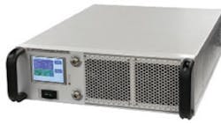
The model 2135-BBS3G6QHM (see figure) is actually two amplifiers in one housing. Silicon laterally diffused metal-oxide-semiconductor (LDMOS) technology is applied for frequencies from 20 to 1000 MHz, while gallium arsenide (GaAs) field-effect-transistor (FET) technology used for the frequency range from about 800 to 3800 MHz.
The amplifier is designed to be a suitable companion to most test instruments, being equipped with a microprocessor-controlled liquid-crystal-display (LCD) front-panel display screen for monitoring and control. The amplifier's operational status is also available along numerous standard interfaces, including GPIB/IEEE-488, RS-422, and TCP/IP Ethernet, which also support remote control via a personal computer (PC) for use in automatic-test-equipment (ATE) setups. The amplifier's linearity and low distortion make it suitable for a wide range of signals. The model 2135-BBS3G6QHM amplifier is designed to operate with both an open-loop gain adjustment mode or in an automatic-level-control (ALC) mode.
The amplifier delivers 80 W minimum saturated CW output power and 50 W minimum output power at 1-dB compression in its low frequency band (to 1000 MHz), with 50 W minimum saturated CW output power and 50 W typical output power at 1-dB compression in its high band (to 3800 MHz). It achieves 46-dB minimum gain at 1-dB compression in the low band and 48-dB typical gain at 1-dB compression in the high band.
The rack-mount amplifier features worst-case gain flatness of 2 dB across its full frequency range. It includes a voltage-variable-attenuation (VVA) range of at least 25 dB to modify the gain, with typical noise figure of 10 dB across the full frequency range. The amplifier hits a typical third-order intercept point of +56 dBm. Second harmonics are typically -40 dBc in the low band and -20 dBc in the high band, while maximum spurious levels are -73 dBc. The maximum input return loss is 10 dB.
The rugged amplifier handles single-phase operating voltages from 100 to 240 VAC, with typical AC power consumption of 600 W. It uses Type N female input and output connectors, measures 19.0 x 5.25 x 22 in., and weighs 50 lbs. It is designed for ambient operating temperatures of 0 to +50C and storage temperatures of -40 to +85C. It has been constructed to meet the typical airborne environmental requirements of MIL-STD-810F, Method 516.5 for shock and vibration and to operate at attitudes to 30,000 ft. per MIL-STD-810F.
The amplifier includes a variety of internal protection schemes: It is protected against input overdrive for levels to +6 dBm; immune to an infinite load VSWR at all phases and amplitudes for a duration of one minute; and can also withstand a load VSWR of as high as 3.0:1 for all amplitudes and phases continuously. MWRF
Empower RF Systems, Inc., 316 W. Florence Ave., Inglewood, CA 90301; (310) 412-8100, FAX: (310) 412-9232, e-mail: [email protected], www.EmpowerRF.com.
About the Author
Jack Browne
Technical Contributor
Jack Browne, Technical Contributor, has worked in technical publishing for over 30 years. He managed the content and production of three technical journals while at the American Institute of Physics, including Medical Physics and the Journal of Vacuum Science & Technology. He has been a Publisher and Editor for Penton Media, started the firm’s Wireless Symposium & Exhibition trade show in 1993, and currently serves as Technical Contributor for that company's Microwaves & RF magazine. Browne, who holds a BS in Mathematics from City College of New York and BA degrees in English and Philosophy from Fordham University, is a member of the IEEE.
