Peak Power Analyzer Checks Pulses To 40 GHz
Power measurements can be deceptive, especially in certain radar and wireless communications systems with high-speed pulsed signals. But the model 8990B peak power analyzer from Agilent Technologies packs the equivalent of a windows XP personal computer into an instrument mainframe with a large touchscreen display. It provides accurate, automated power measurements, as well as a wide range of pulse parametersincluding rise and fall time and duty cycleto assist both defense and commercial wireless researchers in studying short-duration signals for their power characteristics. model 8990B is like a power meter and then some, with an RF measurement range of 50 MHz to 40 GHz and rise-time capability of 5 ns (depending upon the choice of connected power sensor).
The peak power analyzer offers four measurement channels: a pair each for RF and video signals. The RF signals are captured on channels 1 and 4 at maximum sampling rate of 100 msamples/s while video signals are captured on channels 2 and 3 at 3.5 GSamples/s. The RF channels feature a video bandwidth of 150 MHz while the video channels have a video bandwidth of 1 GHz. The analyzer captures signals to a minimum pulse width of 50 ns and at a maximum pulse repetition frequency (PRF) of 10 MHz. The maximum capture length is 1 s, with a maximum of 2 million data points. Amplitude levels on the RF channels are shown on vertical scales from 0.01 to 100 dB/ division, with an offset range of 99 dBm that is adjustable with 0.01-dB resolution. on the video channels, the scales can be set over ranges of 1 mV/division to 1 V/ division or 1 mV/division to 5 V/ division, depending upon the impedance setting and coupling (aC or DC coupled) of the input connectors. Its internal timebase can be set from 2 ns/div to 100 ms/div with 1 ns or better jitter and delta time accuracy of 1 ns.
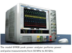
Model 8990B is dominated by its vivid, 15-in. XGA color touchscreen display (see figure). Detected signal traces are shown in the main display area of the screen, which can show as many as four traces: two RF traces and two analog traces (the triggering signal). The results of measurements are shown under the main screen. The touchscreen display simplifies using the 8990B, since it offers a total of 15 different automatic pulse measurements, including pulse repetition interval (PRI) and pulse repetition frequency (PRF). the analyzer is powered by a Core Duo 3-GHz microprocessor from Intel. Pulse measurements can be executed by performing three simple steps: selecting the trigger source, the trigger edge, and the trigger level. All 15 pulse characterization measurements are listed on a soft panel key to the side of the graphical window, for quick measurement analysis. The analyzer can also perform automatic delay measurements as well as automated pulse droop measurements, gauging the amplitude degradation of a pulse top, with values color coded to signal traces.
A pair of new fast-rise-time power sensors, models N1923A and N1924A, have been developed for use with the 8990B peak power analyzer. The former operates from 50 MHz to 18 GHz with 3-ns rise/fall time, while the latter features a frequency range of 50 MHz to 40 GHz with 3-ns rise/ fall time. For both sensors, the power measurement range is -30 to +20 dBm for signals lower in frequency than 500 MHz and -35 to +20 dBm for signals of 500 MHz and higher.
The model 8990B peak power analyzer uses SCPI programming language, and is equipped with LXI-C, RS-232, LAN, and usB 2.0 ports for remote control and data transport. It can be equipped with a removable hard drive for secure installations. A built-in source supplies 50-MHz and 1.05-GHz calibration signals.
Agilent technologies, 5301 Stevens Creek Blvd., Santa Clara, CA 95051; (877) 424-4536, (408) 345-8886, FAX: (408) 345-8474, Internet: www.agilent.com.
About the Author
Jack Browne
Technical Contributor
Jack Browne, Technical Contributor, has worked in technical publishing for over 30 years. He managed the content and production of three technical journals while at the American Institute of Physics, including Medical Physics and the Journal of Vacuum Science & Technology. He has been a Publisher and Editor for Penton Media, started the firm’s Wireless Symposium & Exhibition trade show in 1993, and currently serves as Technical Contributor for that company's Microwaves & RF magazine. Browne, who holds a BS in Mathematics from City College of New York and BA degrees in English and Philosophy from Fordham University, is a member of the IEEE.
