Programmable Pads Set Levels To 18 GHz
PA Series attenuators currently include model PA-124 (with 0 to 15 dB attenuation), which can be programmed in 1-dB steps, and model PA-125 (with 0 to 70 dB attenuation), which can be set in 10-dB steps. Both attenuators can be specified for frequency coverage of DC to 12.4 GHz, with an option to extend the frequency coverage to 18 GHz. In addition, a number of different frequency bands within the DC-to-18-GHz range are available, depending upon a customer's requirements.
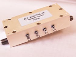
The rugged PA Series attenuators (see figure) employ reliable solenoid-based actuators to switch in different values of attenuation elements into the attenuator's signal path. In the case of the PA-124 programmable attenuator, for example, attenuation elements or cells with values of 1, 2, 4, and 8 dB are used to achieve the total attenuation (when all cells are switched into the signal path) of 15 dB. By using one or more of the cells, any combination of attenuation values can be achieved in 1-dB steps from 0 to 15 dB (with 0 dB the case when no attenuation cells are switched into the signal path). A PA-125 programmable attenuator uses larger-valued attenuation cells of 10, 20, and 40 dB to achieve its 70-dB range and 10-dB resolution.
For the PA-124, the insertion loss is 0.6 dB through 5 GHz, 1.0 dB through 12.4 GHz, and 1.3 dB through 18 GHz. The maximum VSWR for this unit is 1.50:1 through 5 GHz, 1.70:1 through 12.4 GHz, and 1.90:1 through 18 GHz. For the PA-125 programmable attenuator, the insertion loss is 0.5 dB through 5 GHz, 0.8 dB through 12.4 GHz, and 1.0 dB through 18 GHz, while the maximum VSWR is 1.50:1 through 5 GHz, 1.70:1 through 12.4 GHz, and 1.80:1 through 18 GHz.
Any attenuator will have some variations in accuracy as a function of frequency, attenuation, and temperature. The PA Series programmable attenuators are no different. The typical attenuation accuracy is 0.5 dB attenuation per cell for the PA-124 units and 1.0 dB per cell for the higher-attenuation PA-125 units. With regard to actual attenuation settings for a PA-124 programmable attenuator, this means that attenuation accuracy will vary somewhat from the specified accuracy setting when the unit is programmed to an attenuation setting requiring more than one cell (although in some cases, the plus and minus variations may yield improved accuracy).
Still, these are highly accurate attenuators, rated to maintain that performance for more than 1 million switching operations. They can handle 1 W input power (rated at +25C) across their frequency ranges, are equipped with SMA female connectors, and boast switch attenuation states with 15 ms maximum switching speed. Numerous variations of the basic models are available, including for +12 or +28 VDC operation, for pulse latching or with a transistor-transistor-logic (TTL) driver, for operation from DC to 5 GHz, DC to 12.4 GHz, DC to 18 GHz, 4 to 8 GHz, 8 to 12.4 GHz, and 12.4 to 18 GHz. The company uses a set of codes to designate different options, such as a model PA-125-D-TL-1218 for a 0-to-70-dB programmable step attenuator for use from 12 to 18 GHz with 10-dB attenuation steps, +28-VDC coil, and TTL drivers. Contact the company for specific requirements.
RLC Electronics, Inc.
83 Radio Circle
Mount Kisco, NY 10549
(914) 241-1334
FAX: (914) 241-1753
e-mail: [email protected]
About the Author
Jack Browne
Technical Contributor
Jack Browne, Technical Contributor, has worked in technical publishing for over 30 years. He managed the content and production of three technical journals while at the American Institute of Physics, including Medical Physics and the Journal of Vacuum Science & Technology. He has been a Publisher and Editor for Penton Media, started the firm’s Wireless Symposium & Exhibition trade show in 1993, and currently serves as Technical Contributor for that company's Microwaves & RF magazine. Browne, who holds a BS in Mathematics from City College of New York and BA degrees in English and Philosophy from Fordham University, is a member of the IEEE.
