Striking the Right Balance: RF Power Output and Efficiency

Download this article in PDF format.
Efficiency in electronics is a measure of how well a device or system does with the power available to it. For a battery-powered product, it’s easy to tell when it’s efficient, since more efficient products will operate for longer time periods on a given battery charge. With the world moving to portable cell phones and eventually 5G cellular systems, cellular radios with high efficiency will contribute to effective wireless communications networks and longer talk times per charge. High efficiency isn’t confined to just power amplifiers (PAs) within the system, though; it involves all of the components that contribute to minimizing signal losses and power.
Efficiency in an RF/microwave system can be described in its simplest form as the amount of RF/microwave output power that’s produced, such as from a PA, from a given amount of dc input power, such as a power supply or a battery. Although the concept is simple, efficiency may not be easy to determine for an application. That’s because it depends on the type of active device or devices used in a PA, the operating frequency, temperature, the drive level, and even the impedance of the load. Even comparing a transmitter based on an electron-tube configuration, such as a traveling-wave tube (TWT), to a solid-state PA based on the latest gallium-nitride (GaN) power transistors will provide some insight into how efficiency can differ drastically for the same frequency range and output power level.
Achieving high efficiency in an electronic system is a common goal for designers, although it can be quite challenging and may involve many components in the system. Power efficiency is usually associated with an electronic system’s active components, such as the PAs in a radio’s transmitters and low-noise amplifiers (LNAs) in a receiver.
A receiver and its LNAs are always typically powered on and the transmitter and PA are powered on only when signals are being sent to another receiver. It’s the efficiency of the PA, though, that can have the greatest impact on the overall efficiency of a transmit/receive system.
Still, a system’s passive components can also contribute to efficiency. Energy is often dissipated as heat by way of some form of loss. For example, the insertion loss of the input and output coaxial cables and connectors can lower the efficiency of the PA by turning some of its power into heat. Especially for applications that rely on batteries, high efficiency is an important performance parameter and can make a significant difference in an electronic system’s useful operating time.
Efficiency can pertain to many different components within a system, including the semiconductor devices within its PAs. Device-level efficiency refers to the ratio of power applied to the input of the device (dc voltage and current) and the RF/microwave power generated at the output of the device. For a bipolar transistor, dc power is applied to the device collector and the device efficiency is called collector efficiency. For a field-effect transistor (FET) or high-electron-mobility transistor (HEMT), the dc power is fed to the device drain, so in this case, device efficiency is called the drain efficiency.
Classifying Amplifiers
Estimating the efficiency of a high-frequency circuit or system usually starts with its choice of active components, notably amplifiers. A choice of RF/microwave amplifier is usually a compromise between linearity and efficiency, as denoted by the number of different amplifier architectures, such as Classes A, B, AB, C, D, E, F, G, and H.
Class A amplifiers, for example, provide very good linearity, but usually with fairly low efficiency compared to the other amplifier architectures. In practical commercial designs, such as the model CMX902 PA from CML Microcircuits, multiple stages using different amplifier classes may be integrated to combine good linearity with high efficiency (Fig. 1).
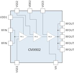
1. Model CMX902 is a three-stage RF PA that combines Class A, Class AB, and Class C stages for good linearity and high efficiency at the same time, all in a 5- × 5-mm package. (Courtesy of CML Microcircuits)
Class A amplifier stages (Fig. 2) are implemented with a single active device, such as an electron tube or transistor, and are often referred to as “single-ended” amplifiers for that reason. They provide low distortion and good linearity for input signal waveforms by supplying bias power and the active device’s conduction at all times. The bias energy (voltage and current) may be varied in response to changes in the input signal waveform, but the power is always on, with the best efficiency usually being 50% or less. For amplifiers, one form of efficiency that considers the amount of power in the input signal waveform is known as the power-added efficiency (PAE).
When the efficiency of an RF/microwave amplifier considers the effects of the amplifier’s gain on the difference between the output power and input power of the amplifier’s signal waveforms, it’s usually referred to as power-added efficiency (PAE). When the gain is high enough, the PAE is typically close in value to the amplifier’s efficiency.
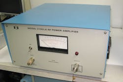
2. Model 3100LA is a robust Class A PA with high linearity from 250 kHz to 150 MHz. (Courtesy of ENI)
To increase efficiency, a Class B PA uses two active devices in what’s often referred to as a “push-pull” configuration. An input signal waveform is power-divided into two signals, with each transistor conducting and amplifying the split half of the input signal waveform for one-half the time, or for one-half or 180 deg. of the input waveform cycle. Then the two halves of the amplified signal waveforms are power-combined and reassembled at the output of the PA. The active devices operate with a 180-deg. phase difference so that their outputs can be combined to achieve a maximum total signal level.
Although this amplifier configuration requires more active devices, the devices can be turned off for as much as 50% of the time to approach an efficiency of 78.5% under ideal conditions. However, the high efficiency from the signal processing and device switching results in less linearity than a Class A amplifier.
Class AB amplifiers represent efforts to combine the high linearity of Class A amplifiers with the improved efficiency of Class B PAs. Here, the two active devices are on for more than “just” 50% of the time, creating an overlapping period when both devices are processing an input signal waveform. This produces a longer duration of amplified signal waveform, with the opportunity to achieve smooth transitions between when each active device is driving the input waveform, albeit with some sacrifice in overall gain compared to a Class B PA architecture.
To create greater efficiency, multiple active devices in Class C PAs conduct for less than one-half of the input signal waveform, or less than the 180 deg. of a Class B amplifier configuration, to save power during the process of boosting the input signal waveform.
By operating active devices with conduction angles as low as 80 deg., a Class C amplifier can achieve extremely high efficiency, approaching 90% in some cases. The tradeoff is that turning on and off and switching among multiple active devices results in high levels of distortion and, typically, the need to add resonant circuits to recover amplified circuits. Class C amplifiers are a good fit for applications in which distortion is not critical, such as for powering pulsed radar signal waveforms.
Class C amplifier configurations are also used in combination with Class B PAs for a “Doherty” amplifier, which is essentially a Class B amplifier in parallel with a Class C amplifier. The PA operates in Class B most of the time to maintain good linearity. However, during signal peaks, it will draw on the parallel Class C stage to provide higher peak power but with less linearity.
Signals of the two amplifier stages are summed at the output of a Doherty amplifier to achieve high output power with somewhat better efficiency than a standard Class B amplifier. Additional amplifier classes attempt to increase operating efficiency for such applications as battery-powered mobile devices, using switched power supplies and driving signals as pulsed waveforms.
In addition to different amplifier classes for choices of operating behavior, amplifier designers have explored creative circuit techniques to boost efficiency. Solid-state amplifiers tend to operate at high efficiency when its active devices are operating close to compression, and techniques to modulate an amplifier’s load (such as amplitude or phase tuning) have been applied to maintain the devices close to their compression points, although this is more difficult to do over broader bandwidths.
In recent years, envelope tracking is a technique that has been applied to increase amplifier efficiency. The amplifier’s bias energy is dynamically adjusted to maintain the amplifier in its peak operating region, with its active devices as close to compression as possible. Rather than the fixed dc supply to a conventional amplifier, an envelope-tracking PA modulates the power supply to the amplifier with a wide-bandwidth waveform synchronized to the input signal waveform to the PA.
Envelope tracking can be implemented in several ways, by means of detecting and monitoring the characteristics of the input waveform to be amplified. The supply voltage, for example, may be continuously adjusted to track the amplitude of the input waveform. For an amplifier with a high peak-to-average power ratio, envelope tracking may require the use of a power supply with an extremely wide dynamic range to optimize efficiency.
In all classes, impedance matching of an amplifier’s active devices to surrounding input and output circuits and components is critical for optimum transfer of signal energy to and from an active device and optimum amplifier efficiency. RF/microwave amplifier designers have long relied on the Smith chart for a graphic depiction of a device’s impedance characteristics, and commercial wideband impedance tuners that can adjust impedance to a device while making measurements on a device in an appropriate test fixture with a broadband vector network analyzer (VNA).
Current manufacturers of such devices include Focus Microwaves and Maury Microwave. Each has extensive lines of fundamental- and harmonic-frequency manual and automatic (controlled with stepper motors) impedance and load-pull tuners. Both companies also offer calibrated impedance tuners for use through millimeter-wave frequencies, to 110 GHz.
New Form of Feedback
In the future, creative use of energy harvesting will no doubt be applied to increase the efficiency of high-frequency (and even portable audio) amplifiers. Energy harvesting is a way to extract RF power from the environment, such as by receiving and converting transmissions from radio stations. It’s being planned as a major source of power for mobile and portable wireless devices like Internet of Things (IoT) sensors and RFID tags, but it can be designed into the supporting circuitry of RF/microwave PAs to contribute to the overall efficiency.
Because of the heat normally dissipated by an RF PA, alternative energy-harvesting approaches are being developed to boost amplifier efficiency. One of these is the use of a thermoelectric generator to transform the heat generated by an amplifier into electrical energy that can be fed back to the amplifier. In a way, the PA’s own initial shortcomings in efficiency are actually being used to increase its operating efficiency.

About the Author
Jack Browne
Technical Contributor
Jack Browne, Technical Contributor, has worked in technical publishing for over 30 years. He managed the content and production of three technical journals while at the American Institute of Physics, including Medical Physics and the Journal of Vacuum Science & Technology. He has been a Publisher and Editor for Penton Media, started the firm’s Wireless Symposium & Exhibition trade show in 1993, and currently serves as Technical Contributor for that company's Microwaves & RF magazine. Browne, who holds a BS in Mathematics from City College of New York and BA degrees in English and Philosophy from Fordham University, is a member of the IEEE.
