How Can 3D-Printed Plastic Waveguides Enable V-Band Applications?
Download this article in PDF format.
Waveguides structures have been well known for ages. Proposed by J.J. Thomson in 1893 and formally calculated by Lord Rayleigh a couple years later, they have been used heavily since World War II in a wide range of microwave and millimeter-wave (mmWave) applications. Such applications include radar, military and civil transmissions, aerospace and satellites, industrial ovens, etc.
The benefits of waveguides over coaxial transmission lines are numerous, but two standouts are very low loss and high power-handling capabilities. The guided wave propagation theory is also well-known, with the ubiquitous transverse-electric (TE) and transverse-magnetic (TM) propagation modes and associated cutoff frequencies, depending on waveguide dimensions (Fig. 1).
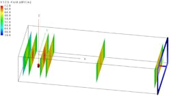
1. This is an example of a plane wave propagation in a waveguide (simulated here with FEKO).
Nevertheless, waveguides are still scarcely used in low-end commercial products. This is mainly due to their cost and size, but also to the relatively low frequency range used in such products. However, the situation is evolving quickly, as mmWave bands find their way into more and more mass-market products, i.e., automotive radar (77 and 24 GHz), Wi-Fi in its 802.11ad version (60 GHz), as well as new 5G cellular bands (24 to 29 GHz and 37 to 40 GHz).
Low-Cost Waveguides?
As a consulting and design house company focused on RF, microwaves, and signal processing, ALCIOM has worked on several projects in which small waveguide sections would make sense. These projects include microstrip-to-antenna transitions, antenna structures, cavity filters, and even as a lower-cost alternative to high-frequency connectors and coaxial cables.
For commercial products, slightly degraded performance can often be tolerated if there’s a significant cost improvement. But what are the options for waveguides structures when standard high-end machined metallic solutions are not adequate? Moreover, which solutions could also provide a fast time-to-market and easy prototyping?
Having these targets in mind, we decided to evaluate the cheapest possible solution: plastic. Of course, this material can be molded for mass production, but it’s also compatible with 3D-printer technologies. Acrylonitrile butadiene styrene (ABS) and polylactic acid (PLA) can be used on ultra-low-cost filament printers, and plenty of other materials are compatible with easily accessible stereolithography printers (STL).
Based on previous tests, we put aside 3D-metal printer solutions too expensive for our goals, as well as “conductive” plastics that provide dc and low-frequency conduction but huge losses at microwave frequencies. Therefore, we decided to test standard plastic materials with a conductive plating on their surface. This article shares our theoretical and experimental results, targeting V-band applications (50 to 75 GHz), and more specifically, the 60-GHz band.
Dimensional Tolerances
Dimensional tolerances represent the first potential difficulty associated with low-cost manufacturing techniques like plastic injection or 3D printing. For relatively narrowband applications, the inner dimensions of the waveguide itself are not really critical—at least as long as the application stays in the center of the waveguide usable bandwidth.
For example, for 60 GHz, the standard waveguide size is WR15, with inner dimensions of 3.76 × 1.88 mm. Such a WR15 waveguide provides a usable bandwidth from 50 to 75 GHz. While a 10% size error will shift these frequencies by 10%, the waveguide will still be usable at 60 GHz.
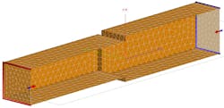
2. To evaluate the impact of dimensional errors, a waveguide-to-waveguide transition was modeled with errors in both axis.
However, the junction between two waveguides manufactured using low-cost processes will inevitably show some misalignments and size variations. What is the impact of such variations regarding insertion loss and return loss? To evaluate this impact, we developed a numerical model of such a junction (Fig. 2). Two waveguide sections were interconnected, but with dimensional errors. We then ran several parametric simulations using the FEKO 3D electromagnetic (EM) solver from Altair with varying dimensional errors (size, offset, angle, etc.) and evaluated the impact on the S-parameters (S11, S22, and S21).
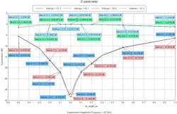
Figure 3 shows a typical result. Here, only one parameter is swept: the height mismatch between the two waveguides. The horizontal axis ranges from −0.5 to +0.5 mm of error. Of course, any dimensional error affects performance, but this simulation reveals that S11 is better than 20 dB as long as the dimensional error is within ±0.3 mm. Assuming that 20 dB of matching is acceptable for the application, such an accuracy is compatible with standard plastic manufacturing processes.
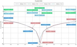
3. This is the simulated impact of a waveguide height mismatch between two sections. The horizontal axis represents the value of the error (−0.5 to +0.5 mm), whereas the vertical axis reveals the impact on reflection and transmission S-parameters.
However, our simulations also pinpointed that other dimensional parameters are more stringent than such a waveguide height error. For example, we performed a simulation of a coaxial-to-waveguide transition. Figure 4 shows the result of this simulation while sweeping the dimension error between the back-short of the waveguide and the position of the coax entry. Here, the same 20-dB mismatch corresponds to a position error of only 0.15 mm (intuitively half of 0.3 mm, as the waves propagates back and forth in this area). Therefore, such a transition will most likely require a tuning screw to achieve acceptable performance.
4. Illustrated is the simulation of a dimensional error on a coax-to-waveguide transition (on the back-short distance).
Building Prototypes
Based on these promising EM simulations, we decided to build some prototypes and evaluate their actual performance. We developed a simple mechanical model for a WR15 section with a length of 20 cm (Fig. 5, top). This model includes two identical half-sections, cut at the middle of the H-plane to limit conductive losses, and two separate flanges. Screws and nuts were used to assemble the prototypes. Of course, other solutions would be applicable for mass production.
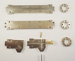
5. The prototypes were built using STL 3D-printed plastic and Ni-Ci electrochemical plating.
We also developed a prototype for a coax-to-waveguide transition (Fig. 5, bottom). It’s based on the same concept with two half-waveguide sections and a separate flange. A semi-rigid coax with a 1.85-mm connector creates the antenna. Two tuning screws allow for compensating the antenna length and back-short position.
These prototypes were manufactured using a standard STL 3D-printing process with a 50-µm layer height. The material used was perFORM (from Somos), which provides good detail resolution as well as reasonable heat tolerance. After 3D printing, the pieces were processed for deposition of a conductive plating on all their surfaces. To check their performance with ultra-low-cost techniques, a standard EMC plating was used (20-µm copper and 10-µm nickel). Figures 6 and 7 show the assembled first prototypes.
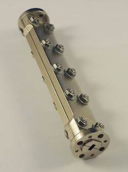
6. This is the assembled waveguide section prototype.
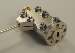
7. The coax-to-waveguide transition prototype was built using a semi-rigid coax and 3D-printed parts.
Test Results
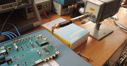
To evaluate the performance of these prototypes, we performed comparative measurements in our labs between these plastic-based waveguide prototypes and high-end waveguide components with similar size and function—both for a 20-cm long section and for a coax-to-waveguide transition. Figure 8 shows the actual test setup. As a generator, we used an evaluation board of the HMC6300 60-GHz mmWave transmitter from Analog Devices. An old but trusted Keysight HP71210C spectrum analyzer with companion HP11974V V-band preselected mixer was used as a measurement receiver.
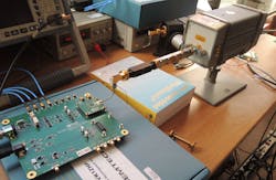
8. Shown is the test bench used to evaluate the S21 performance of the waveguide section.
For the 20-cm waveguide section, the measured S21 performance was nearly identical between the plated plastic 3D-printed prototype and a full metallic WR15 waveguide section. We measured about a 0.1-dB difference, which is far below the measurement uncertainty at 60 GHz. The behavior of this plastic waveguide was therefore very close to its high-end counterpart.
For the coax-to-waveguide transition, and after a quick attempt to optimize the tuning of the two adjustment screws, we measured 1 dB of extra loss. Nonetheless, this difference seems more than acceptable due to the very crude prototyping assembly used for these experiments. The discrepancy probably results more from the very simple mechanical model rather than the 3D-printed material itself.
Wrapping Up
Several papers study the performance of 3D-printed structures for waveguides or microwave/mmWave antennas (see bibliography), using mainly metal 3D printing.
Our experimental work was a simple attempt to use ultra-low-cost techniques (standard STL 3D printers and EMC-type Ni-Cu plating) to build V-band waveguide parts. The simulations presented in this article, confirmed by prototypes and lab tests, show that such a technique allows for performance degradations that are reasonable in comparison to high-end, machined, full-metal waveguides. Additional losses ranging from 0.1 to 1 dB were achieved on the first prototypes, with room for improvement.
Based on these promising results, new solutions could be proposed even for low-volume and low-cost commercial devices, particularly in the 60-GHz band now available for Wi-Fi.
Paui Rousseau is RF Design Engineer, Yannick Avelino is Chief Technology Officer, and Robert Lacoste is Director and Founder of ALCIOM.
Bibliography
Lightweight Waveguide and Antenna Components Using Plating on Plastics, Geterud, E.; Bergmark, P.; Yang, J. (2013). 7th European Conference on Antennas and Propagation, EuCAP 2013, Gothenburg, Sweden, 8-12 April 2013 pp. 1812-1815. https://core.ac.uk/download/pdf/70600449.pdf
3D printed waveguides: A revolution in low volume manufacturing for the 21st century, William J. Otter, Nick M. Ridler, and Stepan Lucyszyn. Centre for Terahertz Science and Engineering, Imperial College London. Division of Time, Quantum and Electromagnetics, National Physical Laboratory. https://spiral.imperial.ac.uk:8443/bitstream/10044/1/45055/2/ARMMS%20Paper%20on%203D%20printing.pdf
Review of 3D Printed Millimeter-Wave and Terahertz Passive Devices, Bing Zhang, Wei Chen, Yanjie Wu, Kang Ding, and Rongqiang Li. International Journal of Antennas and Propagation, Volume 2017, Article ID 1297931. http://downloads.hindawi.com/journals/ijap/2017/1297931.pdf
Attempt of the Metallic 3D Printing Technology for Millimeter-Wave Antenna Implementations, Bing Zhang, Peter Linnér, Camilla Kärnfelt, Pui Lam Tam, Ulf Södervall, Herbert Zirath. 2015 Asia-Pacific Microwave Conference (APMC). https://hal.archives-ouvertes.fr/hal-01299334/document

