A Brief Tutorial on Microstrip Antennas (Part 1)

Download this article in PDF format.
A significant performance element in communication and radar systems—as well as wireless devices—is the antenna. It may be defined as a transducer between a guided electromagnetic (EM) wave propagating along a transmission line, and an EM wave propagating in an unbounded medium (usually free space) or vice versa.1 The antenna is required to transmit or receive EM energy with directional and polarization properties suitable for the intended application.
This multi-part tutorial explores the radiation properties of rectangular microstrip antennas—specifically, the radiation method, coupling of the feed structure to the microstrip radiating element (or elements in the case of array structures), and the simple transmission-line model utilized for design and performance estimates. Parts 1 and 2 of the series explore the single-element, rectangular microstrip antenna. Later installments will examine the properties of antenna arrays constructed from the ensemble of single microstrip elements.
Antenna Characterization
Antennas are characterized and described by classification and descriptive parameters. In addition to microstrip or printed antennas, other classes of antennas are wire (e.g., dipole or loop); aperture (e.g., horns); reflector (e.g., parabolic); and lenses. The microstrip antenna may be considered a wire antenna due to the associated property of current on the radiating element. However, microstrip antennas are commonly granted the distinction of a separate antenna classification.
The most notable antenna parameters and definitions are summarized within Table 1.

In addition to the antenna definitions, understanding descriptive antenna parameters requires a graphical and geometric reference. That reference is provided by the spherical coordinate system as defined in Figure 1.
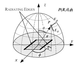
1. Spherical coordinate system.
In the following discussion, geometric planes are referenced with respect to the graphic of Fig. 1. Specifically, the E-plane (y-z) refers to the conditions:

while the H-plane (x-z) refers to the conditions:

The E-field and H-field of the radiated signal lie in the respective planes. Polarization of the radiated signal is defined with respect to the E-field.
For a microstrip antenna, radiation intensity is typically confined to the upper half hemisphere, i.e. above the x-y plane with radiation intensity in the positive z-direction.
Microstrip Antenna Description
The microstrip, or patch, antenna is a relatively new development that was originally patented in 1955 but did not find broad application for almost two decades. Construction of a microstrip antenna embodies a dielectric substrate with a ground-plane conductor on one side and a thin, radiating conductor element on the opposite side (Fig. 2) in which the radiating element is a rectangular conductor attached directly to a microstrip feed line.
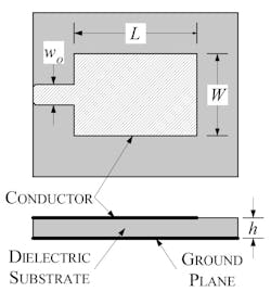
2. Microstrip antenna construction.
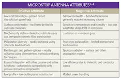
The principal attributes of microstrip antennas are summarized in Table 2.
In a properly designed microstrip antenna, the radiation intensity is in a direction normal to the radiating element (i.e., broadside). For the rectangular microstrip antenna, the length, L, is typically one-third to one-half wavelength long, depending on the substrate relative dielectric constant, which is commonly 2.0 to 10.0. The lower values of dielectric constant yield higher efficiency.
The substrate height, h, is another a critical parameter with respect to efficiency and bandwidth. It’s also important in terms of reducing undesired propagation modes at the conductor edges and within the substrate.
Several techniques are available for the introduction of RF energy to the radiating microstrip via the feed-line structure. In some cases, alterations in the feed-line structure have the potential for attendant changes to the efficiency, gain, and bandwidth of the microstrip antenna. The most common feed structure for the rectangular microstrip antenna is direct attachment at the radiating edge as illustrated in Fig. 2.
The rectangular microstrip antenna geometry is most popular. However, alternate shapes (e.g., circular and triangular), provide utility in certain applications. Thin strips for the implementation of half-wavelength dipoles are attractive for increasing the operational bandwidth. To maintain brevity, the emphasis within this tutorial is restricted to microstrip antennas of rectangular geometry.
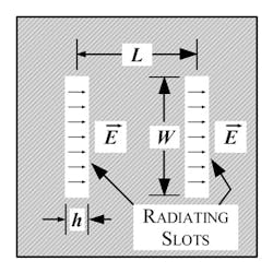
The graphic of Figure 3 represents the rectangular microstrip antenna with the various parameters identified. Note specifically the radiating electric-field configuration at each edge of the microstrip conductor. Because the effective length of the microstrip conductor is a half-wavelength, the electric field is at maximum at the left and right edges due to the effective open circuit and the repeating field pattern at half-wavelength intervals.
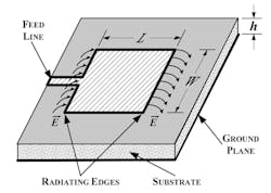
3. Rectangular microstrip antenna—radiating edges.
The radiation intensity is significantly influenced by the conductor length, L, and width, W, and to a lesser extent the substrate height, h.
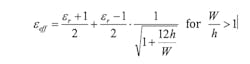
The microstrip conductor is located at the boundary of two dielectric materials: the substrate below the conductor and the air above. Since part of the electric field is located within the substrate material and part in the air, the relative dielectric constant of the substrate must be modified to accommodate the influence of the dielectric boundary. The accommodation is represented by the mathematical definition of the effective dielectric constant.
In addition to the influence of the dielectric substrate and air boundary, the impact of fringing of the electric field at the edges of the conductor must be accommodated. Electric field fringing at conductor edges may be accurately modeled by lumped-element capacitors that effectively increase the electrical length of the conductor at each edge by an incremental length, ΔL. The incremental length is represented mathematically:5
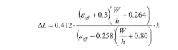
Thus, the effective electrical length of the conductor may be written:

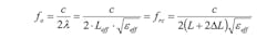
As mentioned earlier, the electrical length of the microstrip conductor at resonance is λ/2. Therefore, accounting for the fringing, the resonant frequency, fo, or corrected operating frequency, frc, may now be written:
The rectangular microstrip antenna is uniquely represented by the transmission-line model, which provides a simple analysis method as well as an intuitive understanding of the radiation mechanics and other operational parameters. It’s also instructive to examine the relative magnitude of the E-field below the conductor to gain additional physical insight. That brings us to Figure 4. Note specifically the E-field fringing at each end of the microstrip line, as well as the dual dielectric occupancy mentioned earlier.
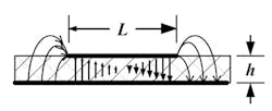
4. Electric field distribution of rectangular microstrip antenna.
The transmission-line model of the rectangular microstrip antenna utilizes an equivalent radiating slot of width W, and height h, to represent each of the radiating edges (Fig. 5).
5. Radiating slot equivalence to microstrip edges.
Each slot may be represented by an equivalent admittance consisting of a conductance and susceptance:

The admittances are separated by a transmission line of length, L, and characteristic impedance, Zo = 1/Yo, thereby forming the equivalent network of the microstrip antenna (Fig. 6).
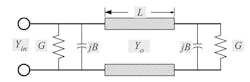
While the equations for the slot admittance are convenient, improved accuracy is achieved by using the equivalent admittance of the radiating slots available from the cavity model.
Cavity Model
Meticulous examination of the microstrip antenna construction discloses that the air dielectric at the sides and conductors at the top and bottom boundaries may define a resonant structure, also referred to as a resonant cavity. Cavity resonators are typically low-loss structures. Therefore, a mechanism must be defined to simulate the radiation loss at each edge of the microstrip conductor.
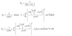
Once again, the radiating slot finds application. However, in the case of the cavity model, the radiation admittance is evaluated from an EM field perspective of significant mathematical rigor that’s not appropriate for this tutorial venue. Notwithstanding, the results of the cavity model are applicable and provide improved accuracy for the calculation of driving point impedance and resonant frequency. Utilizing the cavity model yields the following equations for the calculation of the resonant input resistance of the rectangular microstrip resonator. Note that the ± sign refers to the specific mode field configuration of the cavity resonance beneath the conductor.
References
- Ulaby, F. T., Fundamentals of Applied Electromagnetics, 2004 Ed., Prentice Hall, Upper Saddle River, NJ, 2004.
- Balanis, C. A., Antenna Theory, 3rd Ed., John Wiley and Sons, Hoboken, NJ, 2005, chapter 2.
- Bancroft, R., Microstrip and Printed Antenna Design, 2nd Ed., Scitech Publishing, Raleigh, NC, 2009, pp. 5-6.
- Bahl, I. J. and Bhartia, P., Microstrip Antennas, Artech House, Dedham, MA, 1980, pp. 2-4.
- Balanis, C. A., Antenna Theory, 3rd Ed., John Wiley and Sons, Hoboken, NJ, 2005, p. 818.
- Bahl, I. J. and Bhartia, P., Microstrip Antennas, Artech House, Dedham, MA, 1980, p. 51.

