What’s the Difference Between Microstrip and Stripline?
Download this article in .PDF format
This file type includes high-resolution graphics and schematics when applicable.
Circuit designers choose transmission-line technologies based on a number of factors, including expected high-frequency performance and ease of implementation. Although transmission-line choices include some more exotic varieties, such as coplanar-waveguide (CPW) technology, the decision often boils down to either microstrip or stripline. Recognizing the differences between the two technologies can help nail down the best option.
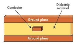
The two high-frequency transmission-line technologies date back to the early 1950s. Stripline was first developed by Robert Barrett of the Air Force Cambridge Research Center in the ’50s as a circuit-based transmission-line alternative for waveguide and coaxial cables. It is essentially a center conductor surrounded by dielectric material with top and bottom metal ground planes (Fig. 1). Stripline is often described as a coaxial cable that was run over by a truck, with its outer ground planes, inner conductor, and isolating dielectric material between the three metal layers.
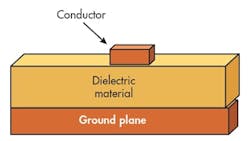
Microstrip is a somewhat simpler structure, with a single ground plane, a conductive trace, and a dielectric layer separating the signal conductor and ground plane (Fig. 2). Stripline conductors are well isolated by the surrounding dielectric material. As a result, they do not radiate and are described as being nondispersive. Because of this, transmission lines in stripline circuits can be closely spaced and densely packed, lending themselves to miniaturization at microwave frequencies. However, with the additional layers, they are more difficult to assemble and manufacture than microstrip circuits with their top-layer conductors.
Microstrip Manufacturing Methodology
Typical approaches to manufacturing microstrip circuits start with a commercial circuit laminate with metallized top and bottom layers using a highly conductive metal, such as copper. The top layer is etched to remove unwanted metal, leaving the traces that form the microstrip circuitry and transmission lines. The bottom metal layer remains as a ground plane.
For stripline circuits, a circuit laminate, prepared in the manner of a microstrip circuit, is usually combined with a prepreg material that has similar dielectric constant (Dk) value—one side is bare dielectric and the other is metallized. Since multilayer circuits may contain many different circuit functions, including RF/microwave and power supply and distribution, multilayer stripline circuits may involve dielectric layers with different materials, selected for the best combination of price and performance for the various functions.
For both microstrip and stripline transmission lines, dimensional tolerances must be tightly controlled. Many high-frequency circuits have to be maintained at 50-Ω, which requires control of a number of factors—including the width and thickness of the conductor, the thickness of the dielectric material, and the Dk value of the dielectric material.
The conductor’s spacing from the two ground planes in stripline is not as critical for maintaining impedance as the spacing of the conductor from the single ground plane in a microstrip circuit. With two ground planes, the width of a conductor for a given impedance in stripline will be narrower than the width of a microstrip conductor for the same impedance. Stripline’s thinner conductors require tighter manufacturing tolerances than microstrip conductors, as well as tighter tolerances in a circuit material’s Dk values.
Because of the second ground plane, the width of a 50-Ω (or any given impedance) line in stripline will be narrower than for a conductor with the same impedance in microstrip. While the inherently thinner lines support greater circuit densities, they also require tighter fabrication tolerances, as well as substrate materials with extremely consistent dielectric constant across a board. For a single-ended (unbalanced) transmission line in microstrip, dielectric losses (defined by a substrate’s dissipation factor) will be less than for stripline, since some of the field lines in microstrip are in air where the dissipation factor is negligible.
The tradeoff for the simplicity of microstrip is its dispersive nature: It tends to radiate wherever there is an impedance transition or discontinuity. Whereas stripline is considered to exhibit fully transverse-electromagnetic (TEM) propagation, microstrip transfers energy by not quite TEM modes. Rather, it uses quasi-TEM modes of propagation in which dispersion occurs as functions of frequency and transmission-line length, compared to the dispersion-free and frequency-independent TEM propagation of stripline transmission lines.
Microstrip also tends to radiate more with increased spacing between transmission lines and ground plane. As a result, microstrip has long been a favored transmission-line format for radiating structures, such as miniature microstrip patch antennas.
Dielectric Differences
Designers must be aware of one key difference in the electrical behavior of the two transmission lines—the Dk value. Since the conductors in stripline are completely surrounded by dielectric material, when modeling stripline transmission lines, the Dk of the circuit material is the numerical value that can be applied to a model. In some stripline designs, such as multilayer circuits, several types of dielectric materials may be used in a circuit assembly. Thus, the Dk value for a given stripline conductor will be a combination of the Dk values for the insulating materials above and below the conductor.
For microstrip transmission lines, the electromagnetic (EM) waves propagate through the conductors and circuit material, as well as through the air above and around the microstrip circuitry. In turn, the low Dk value of air (approximately unity or 1) impacts the effective dielectric constant that influences a microstrip circuit’s modes or propagation.
Consequently, many suppliers of RF/microwave circuit-board materials provide “design Dk” values for their materials, so that designers have a more accurate value of Dk to use for microstrip circuit designs. Since microstrip propagation occurs partially in (lossless) air, dielectric losses in microstrip will be less than those in stripline circuits, although commercial circuit materials are available with almost negligible dielectric losses.
With its embedded conductors, stripline is well-suited for multilayer circuits since signals can be easily routed between layers via plated through holes (PTHs). Designing and assembling multilayer stripline assemblies requires some care, however, since uneven spacing between the top and bottom ground planes in any part of the stripline assembly can lead to unwanted propagation modes, such as a parallel-plate mode. Such a mode enables propagation not just near the signal conductor, but in any areas where the two ground planes can support propagation, creating unwanted signal coupling and interference in densely packed circuits.
Both microstrip and stripline are “well-worn” RF/microwave transmission-line technologies, having been in use for more than 60 years. As manufacturing capabilities have improved with time, so too have the formulations of circuit laminates and prepreg materials, allowing circuits with both transmission-line technologies to be designed and fabricated with high performance through millimeter-wave frequencies.
In fact, some circuit material suppliers, such as Rogers Corp., offer excellent educational tools. Rogers’ “ROG Blog” includes comparisons of different microwave transmission lines, including microstrip and stripline. On top of that, modern computer-aided-engineering (CAE) software programs have made it possible to achieve the performance benefits of stripline and the design and manufacturing simplicities of microstrip with first-pass success.

About the Author
Jack Browne
Technical Contributor
Jack Browne, Technical Contributor, has worked in technical publishing for over 30 years. He managed the content and production of three technical journals while at the American Institute of Physics, including Medical Physics and the Journal of Vacuum Science & Technology. He has been a Publisher and Editor for Penton Media, started the firm’s Wireless Symposium & Exhibition trade show in 1993, and currently serves as Technical Contributor for that company's Microwaves & RF magazine. Browne, who holds a BS in Mathematics from City College of New York and BA degrees in English and Philosophy from Fordham University, is a member of the IEEE.
