


With 5G communication on its way, over-the-air (OTA) testing has become a focus of many companies throughout the industry. That’s because 5G test methods will almost certainly extend beyond traditional cable-based methods. One firm that has entered into the OTA test fray is Wireless Telecom Group, which demonstrated its own OTA test system at IMS 2018. Wireless Telecom Group is comprised of Boonton Electronics, CommAgility, Microlab, and Noisecom.
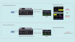
Figure 1 shows an illustrated block diagram of an OTA test system. This test system consists of a noise source, a test chamber, antennas, and a spectrum analyzer. In terms of configuration, the noise source located outside the chamber is connected to a transmit antenna within the chamber. The receive antennas inside the chamber are connected to a spectrum analyzer on the outside.

1. This OTA test system utilizes a calibrated noise source.
Noisecom is emphasizing the suitability of noise sources for OTA testing. The company notes that “making reliable and repeatable measurements inside any chamber requires the chamber—and test system as whole—to be calibrated and quantified.”
Furthermore, Noisecom points out that “noise sources are ideal for this type of calibration process, as they provide a known source with calibrated data points that can be used to determine cable loss, air path loss, antenna efficiency, and total chamber response. After the system is calibrated and quantified, the same noise sources with known characteristics can be used as a reference source for the device under test (DUT) to receive signals.”