Measuring Modern Pulsed Radar Signals
This file type includes high resolution graphics and schematics when applicable.
Radar technology was once mainly the domain of military users, but it continues to expand into instruments for weather, automotive safety, and even astronomy. Measurements of radar systems are as important as ever, especially as these systems impact so many different applications.
Fortunately, improvements in test instruments and measurement techniques have made it possible to accurately measure, analyze, and troubleshoot radar systems with many different signal types—both in the frequency and time domains—to help achieve and maintain optimum performance levels in these radar systems.
Traditionally, radar measurements have required the use of oscilloscope and crystal detector for time domain parameters and a spectrum analyzer for frequency-domain parameters. Measurements were made on pulsed signals and depended on the type of radar system. They involved measurements of pulse width—plus pulse repetition interval (PRI) or pulse repetition frequency (PRF)—along with such parameters as signal amplitude, noise, and interference (depending upon the functions of the particular radar under test).
Modern radar systems continue to evolve, with improvements in range, resolution, and immunity to interference. This has made it possible for radar engineers to employ a wide variety of modulation techniques that were previously unavailable. Along with the growing complexity and sophistication of modern radar systems, the measurement systems for evaluating those systems also become more complex. Accordingly, it is important to keep track of which test systems and capabilities are needed for evaluating different radar systems, since many lives depend upon these systems.
Traditionally, the signals being evaluated during testing of a pulsed radar transmitter consisted of a steady stream of pulses. This may not be the case in modern radar systems, as pulses are generated in a number of different ways in newer systems. Modern radar designs typically strive to transmit pulses at minimum power levels while receiving return signals at greatly reduced levels.
A number of different techniques may be used in the process, including the use of modulating pulses to achieve pulse compression, varying the PRI to eliminate range-gate blind spots, and using narrow or frequency-chirped pulses. New test equipment is needed to evaluate a growing number of radar system parameters, with such capabilities as segmented acquisition memory, streamed recording, and advanced triggering techniques. Fortunately, the latest generations of spectrum analyzers and oscilloscopes have been designed to meet the measurement needs of both new and emerging radar systems.
Some modern radar measurements are more appropriate in the frequency domain, while others are better made in the time domain; some may require the use of testing in both domains. Frequency-domain testing with a spectrum analyzer may include testing for out-of-band spurious emissions, which can be caused by many parts of a radar system [including digital-signal-processing (DSP) and control software]. Spurious signals can also be caused by hardware. Spectrum measurements of transmitted signals help detect transients and memory effects. Spectrum analyzer measurements also measure signal power levels which involve a channel of interest and adjacent channels as well as the behavior of frequency-hopped signals.
Single-pulse measurements are commonly performed in the time domain, with an oscilloscope, to evaluate the quality of individual pulses. Time-domain testing is also performed for pulse-width and PRI measurements, rise/fall-time measurements, and analysis of analog modulation.
Many modern radar transmitters may require multiple-pulse testing to reveal differences between the individual pulses that can cause false or “blurred” radar readings. This can be achieved via parametric trend analysis, whereby measurements are parameterized so that all linear measurements can be made on a common pulse model. Once the model has been determined, parameters for each pulse can be measured.
Linear radar pulse measurements that can be made with this model include rise and fall times, PRI, and pulse width. Statistical analysis is then applied to calculate variations in the ensemble of detected pulses. Pulse-to-pulse trends, histograms, and even frequency-domain analysis can be applied to highlight potential problems in a radar system.
Since finding a radar pulse can be an algorithm-intensive process, increased computing power is needed for modern pulse measurement solutions. This is especially true when measuring pulses over a wide range of amplitudes, since noise can make it difficult to detect and analyze pulses at lower amplitude levels.
This file type includes high resolution graphics and schematics when applicable.
Reliability Versus Speed
This file type includes high resolution graphics and schematics when applicable.
For standard pulse-detection algorithms, a basic tradeoff exists between reliability and speed. Greater reliability means that the algorithm takes a longer time to complete—even though the pulse measurements may operate only on data already stored in memory. Modern pulse analysis methods speed up the process of characterizing transmitter designs by taking advantage of the increased computing power of modern test and instruments, with their capabilities to quickly crunch through multiple algorithms.
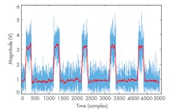
For example, one method applies four separate algorithms to perform pulse detection: Magnitude Histogram, Local Statistics, Moving Average (as shown in Fig. 1), and Least Squares Carrier Fit. Each of these algorithms is within the DSP circuitry of the test instrument one at a time, with the simplest and fastest to perform first. If a pulse is found at any time, the process ends. This method ensures that a pulse is detected and its amplitude measured as accurately (and quickly) as possible.
Powerful test instruments are required to efficiently and quickly run such algorithms. Many of today’s high-performance spectrum analyzers include advanced algorithms like these on board. Often they have built-in tools for making dozens of measurements automatically on each pulse. These include new measurements, such as impulse-response (also known as time sidelobe) and delta frequency measurements. Many modern high-performance spectrum analyzers also include new statistics capabilities, such as pulse trending and histogram analysis, to better understand variations in pulse parameters.
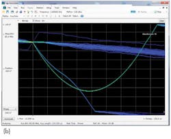
Some modern spectrum analyzers provide the rapid processing power to analyze as many as 390,625 spectrums/s (Fig. 2). In addition, some time-domain visualization tools contained within modern spectrum analyzers can analyze as many as 50,000 time records/s to provide another high-speed method for analyzing radar pulses.
Real-time spectrum analyzers provide the means of measuring rapidly changing signals, such as signals that mat change in real time. This latest-generation of spectrum analyzers samples incoming RF/microwave spectrum for analysis in the time domain and converts the input signal information to the frequency domain by means of Fast Fourier Transform (FFT). Real-time spectrum analyzers can make it possible to observe signals that are difficult to detect with a standard spectrum analyzer, such as infrequently occurring signals or low-power signals that are nearby other signals within a spectrum of interest.
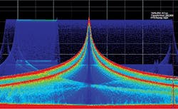
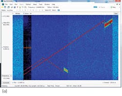
As an example, Fig. 3 shows a swept DPX display spanning several gigahertz. The display reveals a large low-frequency-modulated (LFM) chirp pulse, as well as (left to right) a lower-power continuous-wave (CW) pulse, two even lower-power LFM chirps, and three other pulsed signals.
For time-domain analysis of pulsed signals, displays are available in modern instruments for showing amplitude, frequency, and phase versus time in real time (Fig. 4). Such display capabilities make it possible to visualize many signal artifacts not readily apparent in a frequency-domain view.
In addition, some present-day test equipment provides the capability to correction frequency- and time-domain displays in one package, essentially combining a spectrum analyzer and an oscilloscope within a single instrument enclosure. To correlate the measurements of time and frequency in real time, a measurement system is needed with appropriate sample rates, bandwidth, and memory depth that can be applied to fully characterize pulsed radar systems.
Once a signal artifact has been detected visually, triggering can be used to isolate it so that further analysis can be made. For long signal acquisitions, triggering makes use of the acquisition memory more efficiently. This is especially true for pulsed RF/microwave signals, since the “off” time is rarely used, although it almost always makes up a majority of the signal playback time. Advanced triggering capabilities in modern instruments make it possible to trigger on signals within signals, as well as to use numerous trigger qualifiers across different time, frequency, and amplitude parameters.
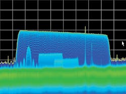
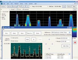
Having access to more trigger types can simplify the evaluation of complex signal effects. As shown in Fig. 5, a frequency-mask trigger (FMT) can act as user-defined monitor for multiple frequencies. Time-qualified triggering provides a way to trigger on events of specific user-defined duration. Along with hold-off features, this can help eliminate false triggering.
Frequency-edge triggers are very useful because they not only serve real-time testing by triggering real-time measurements, but enable all of the other measurements in an oscilloscope. Using different types of triggers with trigger input and output signals can make it possible to synchronize multiple signal instances in a radar system.
Modern real-time spectrum analyzers and software provide the means for capturing “runt” pulses, which are transient signals buried among larger signals within a bandwidth or short pulses found within a string of longer pulses. Runt pulses often overlap in time and frequency with the desired signal, making them especially hard to trap and separate.
An amplitude-qualified trigger provides the capability to capture runt signals, since an analyzer with this type of trigger can isolate pulses of specific amplitude and/or width within a pulse train. Advanced triggering capabilities make it possible to detect transient signals in many radar systems, whether for analysis of radar system instability, glitches, or interference.
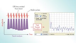
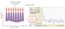
Modern statistical methods can be applied to explore the nature of a pulse’s modulation and reveal information about its source. This is often done by converting amplitude trend data from the time domain to the frequency domain via FFT. The spectral view can show whether modulation occurs at a single frequency or is at multiple frequencies. An FFT performed on pulse signals and the instrument’s spectral view of the amplitude trend data reveal 4-kHz modulation on a pulse (Fig. 6). The low modulation frequency means that it is not coming from incoming power, but more likely from a switching power supply.
Modern radar systems—whether for commercial, industrial, or military applications—continue to grow in complexity, and so, too, must the measurement solutions for these systems. But modern spectrum analyzers and oscilloscopes use a variety of new methods that let them accurately measure, test, analyze, and troubleshoot systems with varying signals. Such techniques employing real-time analyzers and the use of test software can greatly help to simplify these challenging measurements of pulsed signals, both in the frequency and time domains.
This file type includes high resolution graphics and schematics when applicable.
