Measurements Help Minimize EMI and RFI
Download this article as a .PDF
Electronic devices operate in a world of electromagnetic (EM) fields of various strengths. Each device is not only subject to interference from those EM fields, but may itself be a source of EM interference to other devices. EM interference can be conducted or radiated, either degrading or disrupting the performance of an electronic device.
Lower-frequency EM interference, such as from power lines, is usually referred to as electromagnetic interference (EMI). Higher-frequency EM interference, such as from radio waves, is known as radio frequency interference (RFI), although the two terms are often used interchangeably. Electromagnetic compatibility (EMC) refers to the fact that an electronic device has been found to operate effectively in this world of EM fields, not causing interference and not affected by the interference around it.
EMI/RFI can be conducted or radiated, and even the most well-conceived circuit layouts can fall prey to their effects. But by the use of software design tools and by performing EMI measurements throughout the design process, it is possible to avoid the frustration of repeated design cycles in pursuit of EMC.
Sources of EMI and RFI are everywhere. EMI is typically generated by fast switching electronic devices, such as switch-mode power supplies, that produce harmonic signals that propagate along the conductors of an electronic device. They can appear in the forms of common-mode noise (where it propagates on multiple conductors at the same time and in the same direction) or differential mode noise (where it travels along opposite directions on signal and ground lines).
Anyone who has driven under power lines while listening to an automotive AM radio has likely experienced the effects of RFI as static and noise on the radio. Interactions between multiple EM fields can cause EMI and RFI. In the case of the AM radio, low-frequency EM emissions from the power lines are radiated into the radio’s antenna and its connected electronic circuits, with the power line’s EM fields transferred to the AM radio by induction. EMI and RFI can also result from conduction, which is the flow of EM energy along a physical path, such as from an electronic device’s own power line and into its transmission lines.
Design engineers coping with the modern demand for continued circuit miniaturization and hoping to achieve EMC compliance must create compact circuits that not only function properly while surrounded by external sources of EMI and RFI, but themselves do not generate EMI and RFI. To understand if an electronic device is a source of EMI and RFI, its own emissions must be measured across a wide enough frequency range so that several harmonic frequencies are included.
The measurement equipment, which includes an RF field probe and test receiver or analyzer, must have the sensitivity, bandwidth, and measurement resolution to detect and identify interference emissions from an electronic device under test (DUT). Such measurements must be performed in a controlled environment shielded from EMI and RFI, such as an anechoic chamber.
A DUT’s power supply and power circuitry can be a source of conducted EMI, while higher-frequency components (e.g., oscillators and transmission lines) can function as antennas and produce unintended RFI emissions. Some levels of EMI and RFI will be present in almost every electronic device. But through well-designed circuit layouts, proper grounding, and shielding (when necessary), those levels can be minimized.
The other side of EMI/RFI is determining a device’s immunity to interference—essentially, its capability to function properly in the presence of certain known levels of EMI and RFI. A device’s tendency to malfunction in their presence is known as its susceptibility. Because the use of radio frequencies varies from region to region around the world, different levels of EMI and RFI at different frequencies can cause disruptions in a device’s performance depending upon the region, and different measurement procedures are developed to establish EMC compliance for each region.
Of course, by performing EMI/RFI measurements and software simulations during various stages of the design process, it is possible to know more about a circuit’s tendency to perform as an emitter as well as its susceptibility to other sources of EMI and RFI. Failing an EMC compliance test can be costly, resulting in time-consuming rework of a circuit layout without a guarantee of passing the next test.
Earning EMC
The process of achieving EMC for an electronic design involves preventing the negative effects of EMI through EM simulation and exacting measurements. Whenever possible, EMC is a goal that should be reached with the minimum number of additional components (EMI filters and connectors, for example) and few additional materials (such as shielding gaskets). At times, however, these additional components and materials cannot be avoided for full EMC.
Once a manufacturer is confident that an electronic design can meet the EMC requirements for a particular region, the design must pass the regulations for a particular market region. Australia, Canada, the European Union (EU), and the United States each have their own regulations for EMC. Internationally, the International Electrotechnical Commission (IEC) is one of three global organizations concerned with worldwide EMC standards for measurement of EMI and RFI, along with the International Standards Organization (ISO) and the International Telecommunication Union (ITU). The Comite International Special des Perturbations Radio (CISPR, or the International Special Committee on Radio Interference) is an organization within IEC devoted to analyzing and combatting RFI, essentially at frequencies above 9 kHz.
In the U.S., regulations for EMC are set largely by the Federal Communications Commission (FCC), with different rules applying to different types of products. For RF products, the FCC’s Code of Federal Regulations (CFR), Section 47, Part 15 rules for unintentional radiators apply, although Section 47, Part 18 rules are used for equipment operating in industrial-scientific-medical (ISM) frequency bands. In the U.S., medical equipment is exempt from FCC rules for EMC and is controlled by standards set by the Food & Drug Administration (FDA) and defense-electronics equipment must meet demanding military standards, such as MIL-STD-461E and MIL-STD-464.
Measuring Interference
Measurements for EMI/RFI seek to determine if a device is a source of EM radiation or if it is susceptible to the EM fields around it. In both cases, measurement equipment must be highly sensitive in order to detect low levels of EM. At the same time, it must be highly accurate, so as to comply with highly detailed test requirements established by the various EMC standards organizations. Programmability and the use of measurement software can speed and simplify the process, storing settings that are repeatedly used as part of standards-based measurements.
Tracking down the causes of EMI and RFI during the design process requires diligence, perseverance, and patience—and having an anechoic chamber doesn’t hurt. On a smaller scale, it is possible to assemble a measurement enclosure that is lined with EMI absorbing materials, shielding gaskets, and shielded connectors that blocks EMI and RFI from sources outside the enclosure and allows meaningful measurements of a DUT’s radiated EMI and RFI energy. Such enclosures are also commercially available from a number of sources, generally the same companies that produce EM field probes and EMI/RFI analyzers for EMC precompliance and compliance measurements.
Testing for EMI and RFI emissions or immunity requires a number of different tools in addition to a shielded test environment. These include a test receiver or analyzer with suitable bandwidth and sufficient sensitivity to detect low-level signals; a line impedance stabilization network (LISN) connected to a DUT for measuring conducted emissions; a signal generator to provide the types of interference expected; and an antenna or EM field probe for measuring radiated emissions. Depending upon the EMC compliance tests required, additional hardware may be needed, such as high-power amplifiers to boost test signals to power levels defined by the compliance standards.
For EMI and RFI immunity testing according to IEC standards, for example, a test system would require a test receiver or analyzer, a signal generator, a power meter, a power amplifier, and a test antenna. The instruments should all cover a frequency range of interest for a particular DUT, and the signal generator should be capable of producing the various modulation formats—e.g., amplitude modulation (AM) and pulse modulation—that are defined in a particular IEC standard. The test analyzer or receiver should provide a wide dynamic range, with low noise floor and high sensitivity to detect low-level signals; a high-enough intercept point to handle higher test power levels; and suitable bandwidth to meet the requirements of a particular standard.
For the number of measurements required, a candidate EMI receiver should provide high-speed testing, but it also must be highly accurate in compliance with applicable EMI standards. It should be characterized by extremely low displayed average noise level (DANL) and provide the analysis bandwidths needed for the EMI tests.
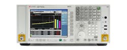
The N9038 MXE EMI receiver (see figure) from Keysight Technologies is an example of such an instrument, with versions covering frequency ranges of 3 Hz to 3.6, 8.4, 26.5, and 44 GHz. It provides all the CISPR analysis bandwidths and delivers a typical DANL of −160 dBm, with a generous assortment of preselector filters and a built-in preamplifier for low-level troubleshooting.
This is one example of a number of excellent EMI receivers on the market, from such suppliers as AFJ Instruments, ETS Lindgren, HV Technologies, Rohde & Schwarz, and Wavecontrol S. L. Rohde & Schwarz, for example, offers a variety of EMI test receivers, for both precompliance and full compliance testing.
The company’s ESR test receiver combines an EMI receiver and real-time spectrum analyzer in one package, with versions covering frequencies of 9 kHz to 3 GHz and 9 kHz to 6 GHz. And for those who want to leave the testing to someone else, companies are available for performing EMI site surveys as well as compliance testing to many international standards, such as F2 Labs and Keystone Compliance.
Prior to testing, a great deal of time can be saved in the design process through the use of software tools, notably EM simulation software that can model the expected EM behavior of a high-frequency circuit prior to assembling a prototype for the first time. Both 3D EM simulation tools and mathematics-based modeling tools can use a computer to predict where disturbances from EMI and RFI will occur, allowing a user to make modifications to the design in search of a solution prior to assembling a circuit.

About the Author
Jack Browne
Technical Contributor
Jack Browne, Technical Contributor, has worked in technical publishing for over 30 years. He managed the content and production of three technical journals while at the American Institute of Physics, including Medical Physics and the Journal of Vacuum Science & Technology. He has been a Publisher and Editor for Penton Media, started the firm’s Wireless Symposium & Exhibition trade show in 1993, and currently serves as Technical Contributor for that company's Microwaves & RF magazine. Browne, who holds a BS in Mathematics from City College of New York and BA degrees in English and Philosophy from Fordham University, is a member of the IEEE.
