AWGs Generate Multiple Complex Signals to 4 GHz
Download a PDF version of this article.
Arbitrary waveform generators (AWGs) provide the means to precisely replicate complex waveforms when they are armed with sufficient bit resolution, sampling rate, and sample memory. The AWG5200 Series of AWGs is equipped with a generous measure of all three commodities, with standard sampling rate to 5 GSamples/s (and as high as 10 GSamples/s with 2× interpolation), 16-b vertical resolution, and enormous 2 GSamples waveform memory per channel. It amounts to modular AWGs in 2-, 4-, and 8-channel configurations with the capabilities to directly generate complex modulated signals with carriers to 4 GHz without frequency translation. The high-bit resolution also means that the generated signals will benefit from a -70 dBc spurious-free dynamic range.
Signal generation for RF/microwave test grows more complex according to a number of factors, including the growing number of devices operating within a frequency range of interest and the various modulation schemes that are used to maintain coexistence of different devices within a common frequency range. Realistic test signals must recreate the modulation used by a device under test (DUT) but may also require the reproduction of noise and interference to mimic a DUT’s actual operating environment. Measurements meant to emulate occupied spectrum, whether for military or commercial purposes, can never have enough test sources because the environments they are simulating are filled with literally thousands of RF/microwave signals from such sources as radars, portable radios, and smartphones.
The AWG5200 Series test sources allow a user to specify (and pay for) the number of signal channels needed for a test. While eight is the maximum number of channels per instrument, as many as four AWG5200s can be synchronized (as many as 32 channels) when eight channels are not enough. This can be the case when testing phased-array antenna systems or multiple-input, multiple-output (MIMO) antenna arrays.
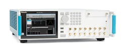
AWG5200 Series arbitrary waveform generators (AWGs) can be equipped with as many as eight independent waveform generation channels at sampling rates to 5 GSamples/s.
The AWG5200 Series of AWGs currently consists of the two-channel AWG5202, the four-channel AWG5204, and the eight-channel AWG5208. Instruments are available with sampling rates as high as 10 GSamples/s, although the base performance level is 2.5 GSamples/s. The AWGs can be supplied with different levels of performance as needed, with a base price of $11,000 per channel for standard levels.
Rethinking Signal Generation
For RF/microwave engineers accustomed to traditional analog signal generation—i.e., starting with an oscillator—an AWG requires a different way of thinking. In an analog source or even a digitally controlled phase-locked-loop (PLL) frequency synthesizer, output signals are defined by the performance limits of an oscillator. In an AWG (even one as elegant as one of the AWG5200 Series sources with its high-speed digital-to-analog converters DACs), multiple numerically controlled oscillators (NCOs), and digital architecture, output signals are essentially defined by an operator’s imagination—within the limits of the digital circuitry.
An AWG can create waveforms according to mathematical relationships (such as sine and cosine) or by deriving those relationships from measurements made on actual signals and then stored as waveform files. Because of the digital, computer-like architecture for generating signals, memory is a valuable resource in an AWG: more memory means longer running times for generated waveforms, especially those with broad bandwidths. For example, when creating a signal waveform at a sampling rate of 5 GSamples/s, 2 GSamples of waveform memory will provide as much as 400 ms waveform time.
Sample rates can be set from 1.5 kSamples/s to 5 GSamples/s (and interpolated to 10 GSamples/s), resulting in a 3-dB sin x/x bandwidth of 2.22 GHz at 5 GSamples/s (and 4.44 GHz when interpolated at 10 GSamples/s). This yields a maximum sinewave output frequency (Fmax) of 2 GHz, which can be raised to 4 GHz with interpolated sampling. Output waveforms to 7 GHz and beyond can be generated, but at reduced output-power levels. The amplitude levels of the output waveforms can be set with 0.1-dB resolution at power levels from -85 to +10 dBm with ±2% accuracy for waveforms from 10 MHz to 2 GHz.
The AWG5200 Series generators have several DAC modes, allowing an operator to choose which mode provides the most suitable output waveforms for an application. A built-in in-phase/quadrature (I/Q) modulator equips the AWGs with fundamental vector-signal generator (VSG) capability and the capability to generate differential output signals for complex modulation signal formats.
Signals can be generated as dc or ac outputs, with dc outputs available in single-ended and differential forms, ac direct outputs in single-ended form. As expected for an AWG with its digital architecture, output performance is defined by mathematical relationships. For example, the single-ended dc amplitude range is 100 mV to 0.75 V peak to peak for single-ended outputs and twice that for differential outputs. An available option raises the top single-ended level to 1.5 V peak to peak. AC direct output levels range from -17 to -5 dBm, with available dc bias of ±5 V at 150 mA. An amplified ac output range is also available, covering -85 to +10 dBm with the same bias power. For ac and dc outputs, the amplitude flatness is ±1 dB at 1 GHz and ±2 dB at 2 GHz. Because waveforms can be defined mathematically, the amplitude flatness can be improved to ±0.1 dB for all frequencies by using predistortion as part of the waveform definition.
For defining waveform transition points or anomalies in an AWG5200 Series instrument’s output signals, as many as 32 markers (four markers per channel) can be placed across the eight channels. The markers greatly simplify operation and measurements, but also require processing power. Each marker uses 1 b of vertical resolution from an output waveform. For example, with no markers active, a waveform’s vertical resolution is 16 b. With one marker active, the vertical resolution drops to 15 b. With two markers active, the vertical resolution is 14 b, dropping to 12 b when as many as four markers are placed on a generated waveform.
Even when compared to single-channel RF/microwave signal sources, the spectral purity of the signals created by the AWG5200 Series AWGs is impressive, with low spurious content and harmonics. However, with the capability to produce multiple signals precisely aligned in time, an AWG5200 is a veritable signal-generation system in a box, replacing one or more racks of signal sources for test applications and simulations where the timing among multiple test tones must be tightly controlled. Each AWG5200 has up to eight separate signal sources, with shielded, independent circuitry per channel for such functions as sequencing and upconversion, resulting in a signal-generation architecture with little or no crosstalk between channels. The only commonality among the channels is the reference clock, used for synchronization.
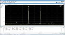
The AWGs provide as many as eight synchronized output channels of spectrally pure waveforms, with typical SFDR performance of better than -70 dBc.
The multiple channels share a common clock for synchronization, and this can be the internal 10-MHz reference source or an external reference oscillator. The standard 10-MHz reference oscillator is more than stable enough for most applications, with typical random jitter of 700 fs (RMS) and typical total peak-to-peak jitter of 10 ps. The stable reference oscillator contributes to low channel-to-channel skew of typically 10 ps or less. In terms of time-domain performance, such as generating short pulses for testing various types of radar systems, the AWG5200 sources can generate pulses with 20% to 80% rise times as fast as 150 ps for minimum pulse widths of 400 ps.
The signal synthesis capability of a single AWG5200 previously required a rack full of signal generators, with synchronization tied to a common stable reference source. In addition to the size and complexity of maintaining individual signal generators, a rack of signal generators can represent a significant investment, not to mention signal analysis instruments also needed with such an instrument installation. The AWG5200 AWGs are code compatible with previous-generation AWGs from Tektronix. Matlab and custom waveforms work across AWG platforms such as the AWG4000, so that legacy software is just as effective.
Setting Signals Straight
Many users will choose to control an AWG5200 from a PC running Tektronix SourceXpress software for remote control and waveform creation. The connection is as simple as inserting an Ethernet or USB cable between the PC and the AWG. The SourceXpress software runs on a PC with Microsoft Windows 7 or newer operating system, and it is powered by a growing library of waveform creation plug-in software modules. These plug-in modules allow for fast design of specific waveform types, including modulated communications signals and radar pulses. In addition, the RF Generic plug-in module allows operators to digitally synthesize modulated signals to generate custom modulated waveforms.
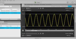
The AWG5200 Series AWGs can be used as stand-alone instruments or remotely controlled with a PC running SourceXpress or other waveform-generation software and waveform files.
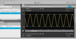
An AWG5200 can also be controlled from its own 6.5-in. touchscreen display. The responsive display offers menu choices and presents images of generated waveforms. Combined with the company’s familiar front-panel rotary control and keypad for data entry, the touchscreen display simplifies the selection of existing waveforms from stored files and the generation of new waveforms based on measured data or on waveform design criteria.
Given the complexity of modern signal waveform environments, many users will rely on waveforms defined by various software programs, such as Excel or Matlab. The AWG5200 series AWGs can work with Matlab .mat files as well as Excel .xls spreadsheets, not to mention even simple .txt text files used to define waveform characteristics. The digital signal sources can also generate waveforms from various .awg and .awgx files created by Tektronix AWG5000 and AWG7000 series AWGs. The AWG5200 AWGs can be programmed for automatic testing using imported waveform files, to create complex sequences of different signal types as needed.
The AWG5200 generators have a removable hard disk drive for ease of changing test setups and for ensuring data security. Trigger inputs on the rear panel enable triggering waveforms with minimum pulse widths of 20 ns and with negligible latency of 2 μs. Rear-panel input ports also accept an external 10-MHz reference oscillator with amplitude of -5 to +5 dBm. An additional 50-Ω input connector accommodates a variable-frequency reference source of 35 to 250 MHz. A rear-panel SMA connector also provides access to the AWG5200’s internal 10-MHz reference oscillator, at a nominal level of +4 dBm. The AWG5200 signal sources are not for everybody. But for testing that attempts to emulate extremely complex signal environments, one (or more) of these instruments may just provide the solution. P&A: $82,000 and up; stock to 4 wks.
Tektronix Inc., P.O. Box 500, 14150 SW Karl Braun Dr., Beaverton, OR 97077; (503)
(800) 833-9200, www.tek.com

About the Author
Jack Browne
Technical Contributor
Jack Browne, Technical Contributor, has worked in technical publishing for over 30 years. He managed the content and production of three technical journals while at the American Institute of Physics, including Medical Physics and the Journal of Vacuum Science & Technology. He has been a Publisher and Editor for Penton Media, started the firm’s Wireless Symposium & Exhibition trade show in 1993, and currently serves as Technical Contributor for that company's Microwaves & RF magazine. Browne, who holds a BS in Mathematics from City College of New York and BA degrees in English and Philosophy from Fordham University, is a member of the IEEE.
