Adapters And Couplers Ride The Millimeter Wave

This file type includes high resolution graphics and schematics when applicable.
Couplers and adapters are necessary links between components in the test and operation of RF systems. As these components are add-ins to the RF signal stream, they produce distortion, attenuation, and delay. Minimizing these performance degraders is a high priority for designers of adapters and couplers, who are preparing their product lines to meet future demands for higher-frequency and wider-band operation. The materials used, quality of construction, finishing, size, and connector type all have significant impact on the performance of adapters and couplers (Fig. 1). For adapters in particular, they impact frequency range, voltage-standing-wave ratio (VSWR), maximum power, and passive intermodulation distortion (PIM). Couplers are affected in terms of frequency range, VSWR, PIM, coupling, accuracy, insertion loss, directivity, and maximum power.
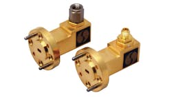
Adapters are used in almost every RF system to bridge the gap between RF components. The most common off-the-shelf RF adapters are coaxial connector adapters, which are either between-series (i.e., between two different standard types of coaxial connector) or in-series (joining two coaxial cable connectors with the same standard type). The goal of between-series adapters is to provide a convenient transition between common coaxial connector types, minimizing length while providing good electrical performance, small size, low VSWR, and broadband coverage. Other RF adapters, such as waveguide-to-coaxial adapters, are offered by Anritsu Co., Ducommun Technologies, and Sage Millimeter (Fig. 2).
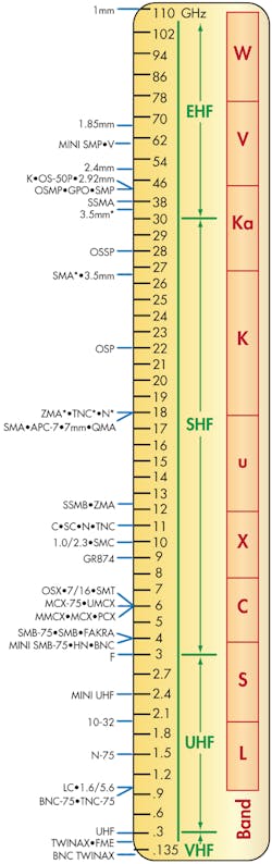
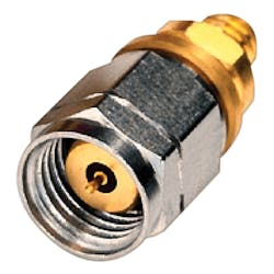
Most between-series adapters are made of machined stainless steel with a passivated finish, nickel-plated brass, and gold-plated brass. The insulators are commonly tetrafluoroethylene (TFE), teflon, polytetrafluoroethylene (PTFE), polyethylene solid/foam, and even air. They are all commonly used as dielectrics for different frequency range and environmental applications. The contact pins are made of copper, gold, or—for high-frequency applications—beryllium copper with gold plating. An adapter’s connector type is the major limiting factor in frequency performance, as larger types of connectors cannot support transverse-electromagnetic (TEM) modes for higher frequencies (see figure). Modern adapter types are constructed with sufficient precision, refined materials, and small dimensions to allow for VSWR as low as 1.2:1 to 110 GHz. Pasternack and Agilent (Fig. 3), for example, has a range of adapter offerings into the 1.0-mm and 1.85-mm adapter range with operation to millimeter-wave frequencies. To avoid being the limiting factor in a design, adapters are being forced to outpace the coupler market in maximum frequency and performance.
Couplers, for their part, are used in a variety of military, space, telecommunications, and test/measurement systems to extract a portion of the transmission (Tx) or reception (Rx) signal, the coupling factor. Specifically, directional couplers are designed with the ability to extract a significant portion of only the Tx or Rx, depending upon how it is configured (known as directivity and isolation). Directional couplers are created by placing a conducting (often metal) coupling structure in proximity to the main transmission line of operation. The coupling structure’s dimensions and the materials used are designed specifically to achieve the frequency response for the desired application.
Traditionally, directional couplers only came in coaxial connectorized models. But modern directional couplers are offered with through-hole, plug-in, and surface-mount connectivity. The transmission lines and coupling structures are often made using printed-circuit-board (PCB) technology to ensure tight tolerances for fabrication, thanks to the availability of laminates with high dielectrics for RF applications. For instance, Mini-Circuits offers surface-mount directional couplers as small as 0.12 × 0.06 in.
Modern directional couplers operate from 0.5 to 60.0 GHz with common coupling factors (assumed negative) of 6, 10, 20, and 30 dB. Some companies, such as Connecticut Microwave, make specialized directional couplers for PIM operation as low as -140 dB with coupling factors from 40 to 65 dB. Like adapters, the maximum frequency is dictated by the quality of materials, machining, and connectivity type. Maximum insertion loss ranges from 2.5 to 0.05 dB with broadband directional couplers sacrificing insertion loss for wider frequency response. Narrowband directional couplers lead with higher directivity ranging from 25 to 10 dB.
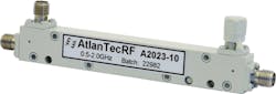
Maximum VSWR ranges from 1.1:1 to 1.8:1 with broadband directional couplers, which generally suffer higher maximum VSWR ratings. In general, the lower-coupling-strength and narrower-bandwidth directional couplers offer better electrical response. Companies like Krytar and AtlanTecRF (Fig. 4) offer directional couplers to 40 GHz, while companies like Narda Microwave have offerings to 60 GHz.
This file type includes high resolution graphics and schematics when applicable.
About the Author
Jean-Jacques DeLisle
Jean-Jacques graduated from the Rochester Institute of Technology, where he completed his Master of Science in Electrical Engineering. In his studies, Jean-Jacques focused on Control Systems Design, Mixed-Signal IC Design, and RF Design. His research focus was in smart-sensor platform design for RF connector applications for the telecommunications industry. During his research, Jean-Jacques developed a passion for the field of RF/microwaves and expanded his knowledge by doing R&D for the telecommunications industry.
