Sequential Rotation Feeds Microstrip Array
This file type includes high resolution graphics and schematics.
Microstrip antennas offer many benefits, including low profile, light weight, and low cost; they are fairly simple to manufacture and easy to integrate with other planar circuits. Unfortunately, microwave antennas are notoriously narrowband in nature, limiting their use for many applications. A number of approaches have been applied to overcome the inherently narrow bandwidths of microstrip antennas—one dating as far back as 1985.1 That technique was based on the use of an aperture-coupled feed structure.
Other attempts have involved different slot shapes in the ground plane of the microstrip antenna,2 with the result being that the antenna’s H slot has larger coupling. The current design incorporates magnetic (H) slots in quadrature, to obtain a wideband circular polarization wave. The H slots are fed by a Wilkinson power divider, using its 90-deg. phase-shifted outputs with the same amplitudes.
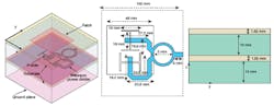
1. These different views show the (a) wideband microstrip antenna geometry, (b) the top view of the antenna element, and (c) the side view of the antenna element.
In recent years, various microstrip antenna arrays have been designed using a sequential rotation technique, with the aim of improving polarization purity, impedance matching, and pattern symmetry across wider bandwidths.3-12 These designs include the use of linearly polarized elements,3-5 circularly polarized microstrip elements,6-10 and feed networks incorporating serial or parallel feeds.11,12 Such approaches can improve the circularly polarized bandwidth, but tend not to impact the axial ratio bandwidth.
For example, the best results registered for axial ratio bandwidth by these researchers was 45%. In this case, a wideband aperture-coupled microstrip antenna was employed as the basic resonant element, although the element is also referred to as an aperture-coupled microstrip antenna in the literature.9 It adopts a branch-line coupler to feed two orthogonally located feeds quadrature to each other. The coupler has a extra load port and a parasitic patch to improve the impedance bandwidth but with a penalty of increased height.
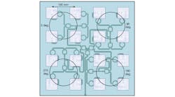
2. The microstrip array antenna is depicted in this layout.
As an alternative antenna design approach, a 4 × 4 circularly polarized microstrip antenna array was designed using a sequentially rotated microstrip line to excite the H-slot aperture-coupled microstrip antenna. Wilkinson power dividers, which provide wide bandwidth and high isolation, provide the signal power division for the feed network. Hence, this microstrip antenna array achieves high gain and better wideband circular polarization characteristic than the design in ref. 9.
Figure 1 shows the antenna element configuration. It consists of three layers: The upper layer is a square patch which serves as radiator; the middle layer is the ground plane with H slots in quadrature; and the lower layer is a feed network with a Wilkinson power divider featuring two quadrature output arms, supplying a 90-deg. phase shift to obtain a circularly polarized wave. After mass simulation and optimization using version Ansoft HFSS10.0 of the High-Frequency Structure Simulator (HFSS) computer-aided-engineering (CAE) simulation software from Ansys, the ultimate parameters used for the microstrip antenna array design are indicated in Figs. 1(b) and (c).

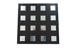
3. The fabricated broadband microstrip antenna is shown in this photograph.
To obtain high gain and good wideband circular polarization performance, the H-slot aperture-coupled microstrip antenna was used as the basic element in an array. A four-element microstrip antenna was created as a subarray without any sequential rotation, and a quartet of four-element subarrays were then fed with a sequential rotation technique using a 90-deg phase shift between each other (as shown in Fig. 2). The distance between adjacent elements is 100 mm (0.67 λ0, where λ0 is the free-space wavelength of the center frequency of interest).
For the sequentially rotated feed network, the feeding point to the full array is at the edge of the substrate. This is because the distance between the reflection board and the feed layer is just 10 mm. This is not easy for an SMA connection with probe feeding, so this structure will exhibit a little higher conductor loss due to the added microstrip line.
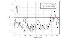
4. These plots show simulated and measured VSWR versus frequency for the wideband microstrip antenna.
The microstrip line feeds of the patch antenna array are arranged for a 90-deg.phase shift with respect to the neighbor with same width of 50 Ω in spite of the 100-Ω microstrip line used in the Wilkinson power divider. The feed network should be carefully designed to confirm that the phase shift sent to each element is at the specific, required values. For example, the corner number should be reduced and the distance between the feed lines should be more adequate for reduced coupling.
To validate the authors’ design approach, a prototype of a 16-element aperture-coupled microstrip antenna was fabricated and tested (Fig. 3). The VSWR was simulated with commercial CAE software, and measured with the assistance of a model E8363B vector network analyzer (VNA) from Agilent Technologies. The simulated and measured VSWR results are shown in Fig. 4.
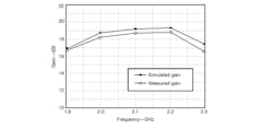
5. These plots show simulated and measured gain versus frequency for the wideband microstrip antenna.
The design shows an impressive bandwidth of 74% from 1.13 to 2.48 GHz with measured VSWR of less than 2.0:1 across the bandwidth. The measured bandwidth shows a slight shift towards higher frequencies than the simulated performance, likely due to measurement errors and fabrication inconsistencies. Figure 5 shows simulated and measured gain versus frequency, with gain of more than 16.6 dBi over an 18.9% bandwidth from 1.92 to 2.32 GHz, and peak gain of 18.7 dBi at the center frequency. Figure 6 shows the simulated and measured axial ratio, indicating a 3-dB bandwidth of 57% from 1.5 to 2.7 GHz.
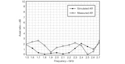
6. These plots show simulated and measured axial ratio (AR) as functions of frequency for the wideband microstrip antenna.
In short, a wideband and high-gain, circularly polarized, aperture-coupled microstrip antenna array is presented here. A 16-element array was obtained by adopting a sequential rotation feeding technique to achieve a wider circular polarization bandwidth than normally possible, using the H-slot aperture-coupled microstrip antenna as an element in the array. The impedance bandwidth (for a VSWR of less than 2.0:1) and 3-dB axial-ratio bandwidth register 74% and 57%, respectively. The microstrip array achieves 18.7-dBi gain at the center of the band and represents a viable candidate for a number of wideband communications applications.
This file type includes high resolution graphics and schematics.
Fangfang Fan, Doctor
Zehong Yan, Professor
Ping Xu, Doctor
Kangbo Tan, Associate Professor
National Laboratory of Science and Technology on Antennas and Microwaves, Xidian University, Xi’an, Shaanxi 710071, People’s Republic of China; 86-29-88202662, FAX: 86-29-88202662, e-mail: [email protected].
Acknowledgment
This work was supported by the Fundamental Research Funds for the Central Universities (Nos. K50511020018 and K5051202028).
References
1. David M. Pozar, “Microstrip antenna aperture-coupled to a microstrip line,” Electronics Letters, Vol. 21, No. 2, January 1985, pp. 49-50.
2. V. Rathi, G. Kumar, and K.P. Ray, “Improved coupling for aperture coupled microstrip antennas,” IEEE Transactions on Antennas and Propagation, Vol. 44, No. 8, August 1996, pp. 1196-1198.
3. T. Teshirogi, M. Tanaka, and W. Chujo, “Wideband circularly polarized array antenna with sequential rotations and phase shifts of elements,” in Proceeding International Symposium on Antennas and Propagation ISAP, Tokyo, Japan, August 1985, pp. 117-120.
4. J. Huang, “A technique for an array to generate circular polarization using linearly polarized elements,” IEEE Transaction on Antennas and Propagation, Vol. 34, No. 9, September 1986, pp. 1113-1124.
5. P.S. Hall, “Application of sequential feeding to wide bandwidth circularly polarized microstrip patch arrays,” IEE Proceedings on Microwave, Antennas and Propagation, Vol. 136, No. 5, October 1989, pp. 390-398.
6. Jeun-Wen Wu and Jui-Han Lu, “2 × 2 circularly polarized patch antenna arrays with broadband operation,” Microwave and Optical Technology Letters, Vol. 39, No. 5, December 2003, pp. 360-363.
7. Tiago Varum, João Matos, Pedro Pinho, et al., “Microstip antenna array for multiband dedicated short range communication systems,” Microwave and Optical Technology Letters, Vol. 53, No. 12, December 2011, pp. 2794-2796.
8. Nasimuddin, Zhi Ning Chen, and K.P. Esselle, “Wideband circular polarized microstrip antenna array using a new single feed network,” Microwave and Optical Technology Letters, Vol. 50, No. 7, July 2008, pp. 1784-1789.
9. Y. Lu, D.G. Fang, and H. Wang, “A wideband circular polarized 2 × 2 sequentially rotated patch antenna array,” Microwave and Optical Technology Letters, Vol. 49, No. 6, June 2007, pp. 1405-1407.
10. H. Evans and A. Sambell, “Wideband 2 × 2 sequentially rotated patch antenna array with a series feed,” Microwave and Optical Technology Letters, Vol. 40, No. 4, February 2004, pp. 292-294.
11. Aixin Chen, Yanjun Zhang, Zhizhang Chen, et al., “Development of Ka -band wideband circularly polarized 64-element microstrip antenna array with double application of the sequential rotation feeding technique,” IEEE Antennas and Wireless Propagation Letters, Vol. 10, 2011, pp. 1270-1273.
12. E.A. Soliman, S. Brebels, E. Beyne, et al., “Sequential-rotation arrays of circularly polarized aperture antennas in the MCM-D technology,” Microwave and Optical Technology Letters, Vol. 44, No. 6, March 2005, pp. 581-585.
