Microstrip LPF Boasts Ultrawide Stopband
This file type includes high resolution graphics and schematics when applicable.
Lowpass filters (LPFs) with wide stopbands are often required in high-frequency communications systems to suppress unwanted harmonic and spurious signals. To meet some of these requirements, a compact LPF based on triangular patch resonators and a butterfly patch resonator with two 120-deg. radial wing patches was developed to provide ultrawideband (UWB) signal rejection.
In demonstrating the design, a microstrip filter with 3-dB cutoff frequency at 1.78 GHz was designed, fabricated, and characterized, and was found to achieve an UWB stopband of 158.2% for suppression of unwanted signals as high as the 12th harmonic signals. The fabricated filter measures just 14.5 × 18.0 mm2, which corresponds to 0.133λg × 0.165λg, where λg represented the guided wavelength at 1.78 GHz.
Planar LPFs are often required in communications systems where higher-frequency spurious and harmonic signals must be rejected. A conventional approach for realizing a microwave LPF involves using high-to-low-impedance lines with shunt stubs and semi-lumped circuit elements.
Unfortunately, while these components combine for good stopband rejection with relatively flat filter rolloff characteristics, they combine for large package sizes.1,2 As a result, techniques to reduce the filter size and enhance the performance have been widely studied in recent years.3-7
By cascading multiple stepped-impedance hairpin resonators, an LPF with sharp rolloff characteristics and wide stopband suppression resulted.3 Unfortunately, the design approach also results in large size and increased passband insertion loss. By cascading multiple semicircular and semielliptic patch resonators, wide stopband suppression was achieved in an LPF design.4
Once again, however, this approach suffered in electrical performance when it was made in a small size. To further improve stopband performance, one group of researchers proposed an LPF by cascading inductive-capacitive (LC) resonant structures and transformed radial stubs.5 Unfortunately, this method results in large circuit size and increased design complexity.
In one LPF design approach, conventional low-impedance stubs were replaced by the radial stubs to realize a wide stopband rejection.6 But the rolloff performance was not ideal and further improvements were needed in stopband bandwidth. One LPF design effort involved the use of a defected ground structure (DGS) and multilayer circuit techniques,7 but, again, this approach increased the LPF circuit complexity.
As part of an effort to realize a microstrip LPF with small size and UWB stopband, both triangular patch and butterfly patch resonators were used in the design. Meandering transmission lines were also employed to achieve a reduction in filter size. The design approach achieved a compact LPF with UWB stopband from 2.83 to 21.60 GHz with better than 15-dB rejection.
The filter also exhibits low passband insertion loss, with less than 0.3 dB insertion loss in the passband. Also of note, it is small—featuring electrical dimensions of 0.133λg × 0.165λg, where λg is the guided wavelength at 1.78 GHz.
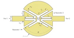
Figure 1 shows the layout of the proposed LPF. It consists of high-to-low-impedance microstrip main transmission lines and two types of resonators, i.e., resonators 1 and 2. Resonator 1 consists of a high-impedance transmission line and a butterfly patch, connected in series. Resonator 2 is a triangular patch. To better understand the design theory, the frequency responses of the two types of resonators were analyzed.
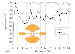
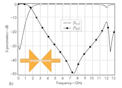
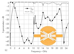
Figure 2(a) shows the frequency response of the filter with resonator 1 only. As can be seen, in addition to the parasitic narrow passband around 7.5 GHz, the filter with resonator 1 only has wide harmonic-suppression characteristics. Thus, to eliminate the parasitic passband and improve the rectangular coefficients, a triangular patch resonator was introduced. Figure 2(b) shows the resonant characteristic of the triangular patch resonator, where the filter loaded with resonator 2 has a wide stopband response and, in the vicinity of 7.5 GHz, one transmission zero which can be adjusted by controlled the size of the structure.
Based on this analysis, both resonators were used to achieve an LPF with wide stopband response. Figure 2(c) shows the filter response curve loading resonators 1 and 2. As expected, the combination of the two resonators results in an LPF with extremely wide stopband characteristics.
This file type includes high resolution graphics and schematics when applicable.
Fabrication Particulars
This file type includes high resolution graphics and schematics when applicable.
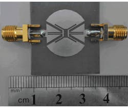
Based on the above analysis, the LPF was designed and fabricated on commercial printed-circuit-board (PCB) material, RT/Duroid 5880 substrate from Rogers Corp. with dielectric constant of 3.38, thickness of 0.813 mm, and loss tangent of 0.0027. The structural parameters for the filter circuit are (as illustrated in Fig. 1): l1 = 2.4 mm, w1 = 2.6 mm, w2 = 0.4 mm, w3 = 0.5 mm, w4 = 1.5 mm, w5 = 0.5 mm, l2 = 5.1 mm, l3 = 5.6 mm, l4 = 3.9 mm, r = 8.5 mm, and θ = 1200. Figure 3 offers a photograph of the fabricated LPF.
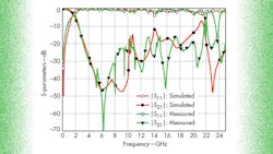
The fabricated LPF was evaluated with the aid of a model N5244A microwave vector network analyzer (VNA) from Agilent Technologies (now Keysight Technologies). Figure 4 offers the simulated and measured S-parameters for the filter, which are in good agreement across the frequency range evaluated. In reference to Fig. 4, the measured 3-dB cutoff frequency is 1.78 GHz.
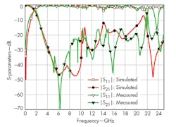
The filter provides out-of-band rejection through the 12th harmonic, as spurious frequencies are suppressed from 2.37 to 18.20 GHz with better than 17-dB rejection. The filter achieves this high suppression in a compact package, with overall size of only 14.5 × 18.0 mm2, which corresponds to an electrical size of only 0.133λg × 0.165λg, where λg is the guided wavelength at 1.78 GHz.
In short, this LPF offers good electrical performance with low passband insertion loss and high out-of-band rejection in a compact size. The LPF has a very wide stopband, and exhibits the capability to suppress 12th harmonic responses based on a cutoff frequency of 1.78 GHz. Such small size and performance make this LPF a candidate for numerous applications in modern communications signals, where higher-frequency spurious and harmonic signals must be suppressed.
Acknowledgment
This work was supported by the Nature Science Foundation of China under Grant Nos. 51365035 and 51164036.
Dong Liang, Professor
Wenqian Xue, Postgraduate Assistant
Zhiyuan Xu, Postgraduate Assistant
Key Laboratory of Universal Wireless Communications, Beijing University of Posts and Telecommunications, Beijing 100876, People’s Republic of China
References
1. David M. Pozar, Microwave Engineering, third edition (Wiley, New York, 2005), pp. 412-415.
2. X.-B. Wei, P. Wang, M.-Q. Liu, and Y. Shi, “Compact wide-stopband lowpass filter using stepped impedance hairpin resonator with radial stubs,” IEEE Electronics Letters, 2011.
3. J.-P. Wang, H.-F. Cui, and G. Zhang, “Design of a compact microstrip lowpass filter with ultra-wide stopband,” IEE Electronics Letters, 2012
4. M. Hayati and A. Lotfi, “Elliptic-function lowpass filter with sharp cutoff frequency using slit-loaded tapered compact microstrip resonator cell,” IEEE Electronics Letters, 2010.
5. M. Hayati, A. Sheikhi, and A. Lotfi, “Compact lowpass filter with wide stopband using modified semi-elliptic and semi-circular microstrip patch resonator,” IEEE Electronics Letters, 2010
6. K.-X. Ma, and K.-S. Yeo, “New ultra-wide stopband low-pass filter using transformed radial stubs,” IEEE Transactions on Microwave Theory and Techniques, 2011.
7. A. Bouteidar, A. Batmanov, A. Omar, and E. Burte, “Design of compact lowpass filter using cascaded arrowhead-DGS and multilayer technique, Asia-Pacific Microwave Conference, 2008.
This file type includes high resolution graphics and schematics when applicable.
