Transitioning to C-Band for Flight-Test Telemetry
The U.S. Government auctioning off telemetry frequency bands has drastically affected the day-to-day operation of the flight-test community—the increased frequency crowding is reducing operational availability. The government responded with new standards for bandwidth-efficient modulation schemes to “pack” more data bandwidth in the remaining telemetry workspace, allowing the private sector to develop hardware in the new C-band allocations for telemetry.
Telemetry vendors responded first with the spectrum-efficient hardware for both air and ground applications, while the requirements for C-band applications evolved from initial experiments to actual orders.
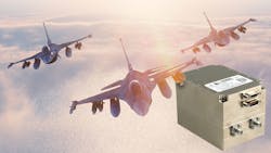
The ground segment in the U.S. has upgraded to be C-band-capable across the country. Of interest, the commercial occupation of their new ownership of the L- and S-bands (D- and E-bands) is regional, with local test ranges still using the L- and S-bands due to the current availability. In areas of the country where frequency crowding occurs, C-band is widely used with equal activity in L-band as well. The wide variation in frequency-band availability has now put the focus on tri-band transmitters for flight-test operations (Fig. 1).
Developing a Tri-Band Transmitter
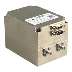
Curtiss-Wright developed a tri-band transmitter to provide a multiband solution in a single unit. Thus, engineers can avoid having to replace units to change bands between test flights or when flying from range to range. The transmitter provides lower and upper L-(D)-band, full S-(E)-band, and C-band in a form factor designed to replace many existing field units.
The unit also includes the latest technology as defined in the IRIG-106-19 standard for advanced range telemetry (ARTM)-compliant modulation, forward error correction (FEC), and space-time compensation (STC), as well as providing independently controlled dual RF outputs. The unit went through a full series of in-house testing as a design-verification step. In addition, the U.S. government has conducted many tests to both validate the hardware performance and become familiar with the new features in a real telemetry environment.
As a result of these tests, there were several modifications and enhancements that included customization, as many of the flight-test ranges didn’t agree on the list of useful features based on their test objectives. Consequently, four variants of the tri-band transmitter now address the desired feature list.
During the test campaigns, several undesirable performance issues were observed and corrected using active compensation. The linearity response of the IQ modulator device (where I is the in-phase component and Q is the 90-degree phase difference) across the three frequency bands didn’t match the manufacturer’s performance data. Unfortunately, the selected IQ modulator had the highest performance currently available amongst the leading suppliers.
The corrective action was to incorporate active band-linearization compensation using a microcontroller to actively monitor temperature and apply compensation factors across the three frequency bands. Another challenge, the RF-power leveling across the three bands, was enhanced with a second microcontroller-based compensation circuit. Control of the transmitter’s overall temperature was also implemented to prevent overheating and component damage.
Interoperability Testing
Much of the funding gained by the sell-off of the telemetry bands was spent on a modern upgrade to receiver offerings for flight-test ranges, with DSP-based receiver designs from several manufacturers addressing the multiband, the STC, and the IRIG 106 Chapter 7 standards. Unfortunately, these efforts by the vendor community were a failure from the standpoint of interoperability testing.
The community assembled for an operability test session at the 2019 International Telemetry Conference in Las Vegas, where the transmitter vendors could test their products against receivers from multiple vendors, allowing them to record the waveforms for future development. Curtiss-Wright was the only transmitter vendor with an IRIG-106-19-compatible transmitter.
As a testament to the accuracy of the IRIG-106-19 standard, the tri-band transmitter performed well, given that receivers from many vendors were able to demodulate the tri-band waveforms at various data rates and using different modulation schemes. This test confirms the stated modulation formulas, the LDPC, and STC coding schema in the IRIG-106-19 standard.
Space-Time Processing Performance
Space-time processing (STP) in transmitters is a method of eliminating intersymbol interference (ISI) between upper and lower antennas in an antenna array. Time delays between the upper and lower antennas is usually caused by differences in cable lengths. Typical propagation delay in coaxial cables can vary from 1.2 to 1.6 ns/foot, depending on the material.
For short cables, the impact of propagation delays is minimal. However, due to the typical scenario of telemetry equipment being added to aircraft after they’re built, long cable(s) are often routed through the vehicle, resulting in differences in the propagation delays.
In the author’s experience, most implementations measure and match the cable delays to minimize the effects of propagation delays. The tri-band transmitter is equipped to delay the STC data pattern from zero to one clock period in increments of 1,024 steps, independently of the two RF outputs, to match the delay of each RF path.
Tests performed with a STC-enabled receiver (STC-ER) have determined that with a timing mismatch of one clock period or less, the STC-ER performs as expected. Mismatches of greater than one clock period result in a significant loss of lock and no data. The vendor of the STC-ER provided a metered representation of the mismatch that provides the user with a visual indication of the balanced time delay with the air system, which makes adjustment of the tri-band transmitter delay feature simple and repeatable.
Forward Error Correction
Today, with the adoption of low-density parity-check (LDPC) code FEC, the IRIG-106-19 standard specifies six varying LDPC coding schemes for improved link margin. However, the improved noise performance isn’t without cost: It increases the bandwidth with the FEC data overhead.
The bandwidth expansion factor (EF) as described in the IRIG-106-19 standard states that regardless of the information block length, or IBL (whether 1024 or 4096 bits), the EF is 33/16 for a channel data rate of 1/2, 25/16 for a 2/3-channel data rate, and 21/16 for a 4/5-channel data rate. This includes the FEC as well as the attached synchronization marker (ASM). The six coding schemes, and their IBLs, are as follows:
1 = Code Rate 1/2, IBL 1024
2 = Code Rate 1/2, IBL 4096
3 = Code Rate 2/3, IBL 1024
4 = Code Rate 2/3, IBL 4096
5 = Code Rate 4/5, IBL 1024
6 = Code Rate 4/5, IBL 4096
As an example, the EF for a 4-Mb/s, NRZ-L stream with LDPC 4 (2/3 rate; block 4096) would result in a data rate of 6.25 Mb/s. The same 4-Mb/s, NRZ-L stream when encoded with LDPC 5 would result in a 5.25-Mb/s data rate; and at the LDPC 1 code rate, the 4-Mb/s stream would result in a data rate of 8.25 Mb/s. The equation is as follows, where R is rate and F is factor:
RTransmitter = RNRZ−L × Fcode rate expansion
Lab experiments with this FEC determined that the encoding performance is well-behaved. The algorithm performs as described in the IRIG standard. Bit-error-rate (BER) performance without and with FEC are shown in Figures 2 and 3.
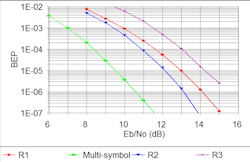
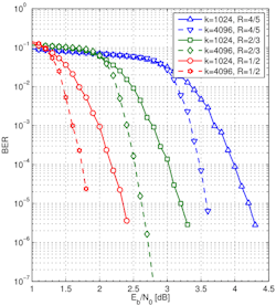
Be advised that the operational region for repeatable performance narrows as the coding gain increases. When applying maximum gain with the 1/2 coding rate, the operation region is somewhat limited down to several decibels.
FEC isn’t useful for all applications, and special consideration should be made before deciding to use this tool to obtain your telemetry data. From the tri-band transmitter perspective, switching the LDPC on and off is easily accomplished by sending a transmitter command of “FE1” to “FE6” to enable a desired code rate, or “FE0” to disable it.
Depending on the ground-state receiver of choice, the changeover from no FEC to FEC being enabled may take several seconds to reconfigure. Planning when to change over in flight will take scheduling to avoid longer loss of data. Certainly, though, FEC works and has been the method of improving link margins for many years.
Thermal Management
With the initial prototype of the tri-band transmitter, deploying it as a “drop-in replacement” resulted in thermal-management issues.
The primary heat-sink path for transmitters is the bottom mounting surface. With the thermal dissipation equally distributed, modules that are farther away from the bottom mounting surface have a higher temperature rise compared to the lower modules. We measured a temperature differential of 20°C between the bottom baseplate and the internal temperature of the top-most module.
Mitigation of the Thermal Rise
Decreasing the thermal resistance between the module sections with overlapping mechanical joints, combined with increased wall thickness on the center power-supply module, reduced the thermal rise from 20°C to 15°C. This increased the RF efficiency with optimized RF tuning through the RF chain, resulting in reduced current draw and an additional 3°C decrease in the temperature differential between the bottom mounting surface and the top-most module’s internal temperature.
We implemented thermal protection with a microcontroller that monitors key areas in the transmitter, controlling thermal dissipation by regulating the output RF power. This control, when activated, throttles back the RF output power when temperature rises above a preset value (typically 75°C). This eliminates the risk of exposing the devices in the top module to excessive temperatures.
Thermal protection is enabled by the end user. To reduce the risk of damage, the user sets the desired temperature threshold and then enables the control through the transmitter communication port. This feature was found to work well and is an easy safeguard against hardware damage when in the field.
Summary
Every development includes new features, problem resolution, manufacturing maturity, as well as surprising results. Development of the tri-band transmitter was no different.
The complete control over the RF output power with independent control of the RF power going to the upper and lower antennas was evidently a useful tool for lab testing. No longer does the test engineer need to carry the variety of RF attenuators to match the RF levels driving the test equipment to perform BER tests.
A simple commanded adjustment of the RF power allows for a smooth RF-level adjustment rather than the manual step attenuator, which eases performance testing. The author historically has not favored the 1-dB step adjustment in RF power. However, after completing this development, the advantage of such a feature is obvious, and the credit goes to the telemetry community for this advance.
The ease of responding to both the 106-15 programming protocol and the 106-19 command protocol was a surprise. From a transmitter vendor’s perspective, the transmitter command listing across the various versions of the IRIG standard has evolved to include well over 60 commands. For the user, having to remember the appropriate protocol for a given transmitter causes delays and inappropriate programming. The tri-band transmitter acknowledges the previous command structure as well as the latest IRIG standard command structure, which saves time and increases typing accuracy for the test engineer.
Throttling back the RF power to limit temperatures in the tri-band transmitter helps avoid hardware damage. In some applications, it’s desirable for the transmitter to “die trying” and continue to transmit through high-temperature events. This isn’t true for flight tests, though, when there are long preflight and flight times during which the temperature-limiting function will save the hardware from damage. This is certainly an advanced feature and welcomed by the flight-test community not to have to turn the transmitter off to cool down.
Thumbwheel and serial-port programming is still required for these flight-test transmitters. The author found those features to be easy to use, presenting very few difficulties in communicating with the tri-band transmitter. The takeaway here is “the simpler, the better,” and it all works. A friendly element of this type of interface is the “?” command, with which the test engineer can print out the many command structures for guidance in choosing the correct one.
Cable-delay matching between the upper and lower antennas is quite easy using the STC balance displays on some of the vendor’s receivers. The delay matching to within 1-bit time is required for STC demodulation performance as the interoperability testing results provided.
As users gain experience using tri-band transmitters, requirements will continually evolve to assure successful reception of data in the current and future frequency bands.
Paul Cook is Director of Missile Systems at Curtiss-Wright Defense Solutions.
Reference
Range Commanders’ Council IRIG-106-19 Telemetry Standard, Chapter 2, and Appendix (performance data provided from the standard for clarity)
About the Author
Paul Cook
Director of Missile Systems, Curtiss-Wright Defense Solutions
Paul Cook is the director of missile systems at Curtiss-Wright Defense Solutions. He has 37 years of extensive design and product-line experience in telemetry systems. He’s held both engineering and management positions in design and development, embedded encryption, RF subsystems and data links, engineering and business management, and program management. Paul has 34 years of experience in the telemetry industry and three years in Information Assurance Type I CCEP certifications.
Cook joined Teletronics in 2007 and worked in the telemetry industry for General Dynamics Corp., Aydin Corp., and L-3 Communications Corp. He obtained a BS degree from the College of New Jersey and has completed various postgraduate courses towards an MBA and Program Management Certifications.
