Why Plastic-Packaged MMIC PAs May be Essential for 5G MIMO Base Stations

Download this article as a .PDF
The introduction of 5G networks will bring higher mobile data rates to more users at once than has previously been possible. Finding the bandwidth to make this a reality will require the industry to meet a number of technical challenges.
Operators will need to move to carrier frequencies above 2.7 GHz to access more spectrum. Multiple-input, multiple-output (MIMO) antenna arrays will be utilized in 5G networks to deliver high data rates to multiple users in dense urban areas. The data rates promised by 5G will also require large instantaneous-signal bandwidths (more than 200 MHz) and the use of more complex modulation schemes.
These challenges will drive demand for small, low-power, efficient, and cost-effective power amplifiers (PAs) that can be used in 64- or even 128-way MIMO antennas. The increased complexity of the modulation schemes used in 5G will also demand that PAs remain highly efficient—even under deep output power back-off (OBO) conditions of more than 8 dB.
These requirements challenge the capabilities of today’s laterally diffused metal-oxide semiconductor (LDMOS) PA technology. In response, the industry has been exploring gallium-nitride (GaN) technology to fill the performance gap. Its uptake has been limited by the cost of the semiconductor material and the use of expensive ceramic packages.
The authors have been working to address these issues, demonstrated by the construction of an ultra-compact 3.5-GHz GaN Doherty PA that can be integrated into a cost-effective QFN plastic package. We used a two-stage GaN core PA monolithic microwave integrated circuit (MMIC). Area-consuming passive networks on integrated passive devices (IPDs) were implemented in the same package.
The Technology Platform
The PAs are 28-V GaN MMICs that are built using a 0.25-μm gate-length GaN-on-silicon-carbide (GaN-on-SiC) technology. We chose a 28-V gallium-arsenide (GaAs) process to build the IPDs, mainly because its thick low-loss metal layer stack enables us to build high-performance inductors with quality factors (Qs) of 40 at 3.5 GHz.
The two types of die are assembled in a 7-×-7-mm QFN plastic over-molded package. To improve thermal resistance, a thick copper lead-frame is used. Standard gold bond wires are used for interconnections.
We use two different high-gain, two-stage GaN PA MMICs that each represent the heart of two different Doherty PA architectures (Fig. 1). The first approach uses a 20-W peak-power asymmetric MMIC, which has a carrier-to-peak size ratio of 1:2 in its final-stage transistors (Fig. 2). The second MMIC is designed for a symmetric PA with 26 W of peak output power. Both use a second-harmonic input short in the final stage to maximize efficiency. Output harmonics are terminated by a parallel-circuit class-E-like matching topology, which is used as the basis of an integrated Doherty combiner.
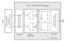
1. The package-integrated Doherty PAs are based on two-stage GaN MMICs. The asymmetric version has an input power splitter and phase offset on the printed-circuit-board, while these features are integrated in the QFN package in the symmetric design.
3. These plots reveal gain and input return loss of the asymmetric (red) and symmetric (blue) Doherty PA board measured at +35 dBm and +30 dBm output power, respectively.
Large-signal measurements show that the PA delivers an output power of 18 to 21 W at 3-dB gain compression (P3dB) from 3.4 to 3.6 GHz (Fig. 4). The maximum line-up power-added efficiency (PAE) is higher than 49%, ranging from 40 to 44% at the high OBO figure of 8.5 to 9 dB. Gain is flat for increasing output power, with about one-dB compression in the main amplifier path before the peaking amplifier sets in.
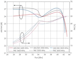
4. CW power-sweep measurements of the asymmetric Doherty PA board were performed. Shown are AM/AM and PAE at 3.4, 3.5, and 3.6 GHz.
The full PA was characterized using a single-carrier 20-MHz LTE signal with 7.2-dB peak to average ratio at an average output power of +35 dBm from 3.4 to 3.6 GHz. The amplifier shows a flat frequency response with a gain that varies from 26.2 to 26.6 dB. The PAE ranges from 41.5 to 43.1%.
The asymmetric Doherty PA achieves a raw adjacent channel power ratio (ACPR) of −24 dBc. Our first results using a digital pre-distortion (DPD) scheme relevant to massive MIMO applications suggest an ACPR of better than −50 dBc with an LTE signal bandwidth of up to 40 MHz.
Measuring the Fully Integrated Symmetric Doherty PA
We built a fully integrated Doherty PA using the symmetric GaN PA MMIC. The GaN MMIC was integrated with GaAs IPDs that contained an input power splitter, input phase offset, and output Doherty combiner matched to 50 Ω. Everything was integrated into one QFN package, enabling a simplified PA demonstration board that only required the addition of decoupling capacitors along with an output dc blocking capacitor (Fig. 5).
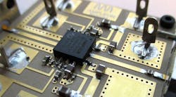
5. Shown is the board that contains the symmetric GaN MMIC Doherty PA, which integrates the input splitter, input phase offsets, and output Doherty combiner with harmonic terminations and 50-Ω matching.
This circuit achieved a higher RF bandwidth than the asymmetric version, with a small signal gain of around 30 dB (refer to Fig. 3). Under continuous-wave (CW) conditions, the PA board yields a P3dB of +44.3 dBm with 52% maximum PAE along with a PAE of 44% at 6-dB OBO. Using a 20-MHz LTE signal at an average output power level of +36.3 dBm, the symmetric amplifier board has a gain of 28.7 dB and PAE of 40% with a raw ACPR of −25 dBc.
Performance Comparison
Figure 6 compares the performance of the two Doherty PA boards. Output power is normalized to peak power.
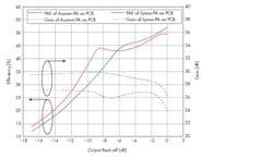
6. These plots illustrate a comparison of gain (dashed) and PAE (continuous) of the complete asymmetric (red) and symmetric (blue) Doherty PA boards normalized to maximum output power (P3dB).
In comparison to the asymmetric version, the symmetric Doherty achieves 2 to 3 dB more gain due to lower losses and an equal power splitting ratio in the input splitter. We also see that the symmetric PA has a PAE that is 1 to 3 percentage points higher than the asymmetric approach (down to 6-dB OBO), due to less impact from the driver transistor’s power consumption.
The measurements also show that the PAE for the asymmetric PA at 8-dB OBO is 8 to 10 percentage points higher than for the symmetric approach. However, this does come at the cost of reduced linearity.
For the symmetric PA, the AM/AM compression is more smooth and the AM/PM curve increases simply monotonically to less than 10 deg. (Fig. 7). For the asymmetric PA, both shapes follow more complex functions. This means that the asymmetric design will need a more complex DPD algorithm for linearization.
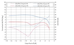
7. This figure shows a comparison of AM/PM (dashed) and AM/AM (continuous) of the complete asymmetric (red) and symmetric (blue) Doherty PA boards normalized to a maximum output power (P3dB).
Conclusions
We built two versions of a Doherty PA board, using MMIC PAs assembled in a low-cost, industrial plastic QFN package. We took the parasitics of the package into account during electromagnetic (EM) simulations to minimize its contribution to overall losses. This allowed us to build a very small board to carry the PA and associated components, which is an essential step towards building massive MIMO antenna arrays for 5G networks.
Acknowledgement
The authors would like to acknowledge the great support within Ampleon that helped to accomplish this work, particularly the teams in Toulouse, Shanghai, and Nijmegen.

