Underlining the Meaning of Linearity

Download this article in PDF format.
Linearity in an RF/microwave component or system is fairly easy to understand in concept: It refers to the ability of a component or system to provide an output signal that is directly proportional to an input signal. As a result, the relationship of the signal input to the signal output as a function of frequency is a straight line.
Achieving good linearity, on the other hand, is not quite so simple, even though it is crucial to preserving key pulse characteristics in a radar and modulation quality in a communications system. Whether it is a frequency mixer, an amplifier, or a complete system, many barriers to linearity must be overcome, often at the expense of some other performance parameter.
The ABCs of Linearity
A simple way to think of linearity for any component is a straight line. For an amplifier, this means that a plot of output power as a function of input power will be a straight line, with the slope of the line equal to the gain of the amplifier. If the gain-vs.-frequency response is fairly even, the line will be straight. A line that is not straight indicates an amplifier is not linear. Of course, most RF/microwave amplifiers tend to tail off in gain at the higher frequencies, resulting in a plot where the line curves downward in the direction representing lower gain
In a wireless communications system, good linearity is essential for both receivers and transmitters, as well as their components. However, poor linearity is most evident when it occurs within the transmitter and a number of its components, including power amplifiers (PAs), frequency mixers, and switches.

Linearity is critical for systems transmitting carrier signals with amplitude modulation (AM) or a combination of AM and phase modulation, such as quadrature amplitude modulation (QAM) or quadrature phase shift keying (QPSK). Nonlinear transmitter performance results in degradation of signal and modulation quality, making it difficult for a demodulator at the receiver to recover the transmitted modulated information.
PAs are usually the first components to check when evaluating a system design for linearity. This is more so than with small-signal amplifiers such as low-noise amplifiers (LNAs), where achieving high output-power levels is less of a concern and the amplifier will not be as apt to go into nonlinear operating conditions.
Because RF/microwave PAs are based on semiconductors, which are inherently nonlinear devices, they fall prey to nonlinear behavior under certain operating conditions. One of these is when boosting the multiple-tone signals commonly used in wireless communications systems. Nonlinear behavior can result in signals mixing and generating unwanted levels of intermodulation distortion (IMD).
The nonlinear behavior tends to worsen as an amplifier approaches saturation, when operating with the highest possible input signals. However, an amplifier operating at saturation is also functioning at its highest efficiency. Thus, using an amplifier in a “backed-off” state at less than peak power to achieve improved linearity represents a classic performance tradeoff—linearity vs. efficiency—facing users of RF/microwave PAs. Various other techniques for higher linearity in RF/microwave amplifiers include the use of feedforward techniques, envelope-tracking technology, digital predistortion (DPD), and analog predistortion to overcome an amplifier’s nonlinear tendencies (see “Linearize Power Amps With RF Predistortion”).
Intercepting Linearity
Several standard performance parameters help expose an amplifier’s potential nonlinearity: 1-dB compression (P1dB) point, second-order intercept (IP2) point, and third-order intercept point (TOI or IP3) point. An amplifier’s compression point refers to an operating condition at which the output signal level no longer increases by the same amount as the input signal level (with the input signal increased as a function of the amplifier’s gain). Amplifiers are usually operated 1 dB below the compression point to preserve linearity and achieve acceptable efficiency.
An amplifier’s IP2 and IP3 points are meant to express either input or output power levels beyond which linearity can be expected. Due to nonlinear behavior, an amplifier will generate a certain amount of IMD as a function of input power. When the IMD increases by 2 dB for every 1-dB increase in input power, it is said to be second-order distortion. When the IMD increases by 3 dB for every 1-dB increase in input power, it is referred to as third-order IMD.
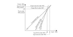
The IP2 and IP3 points are mathematical representations of linearity rather than actual physical power levels. IP2 and IP3 are often described in terms of a logarithmic x-y plot of input power vs. output power (see figure).
The desired amplifier performance is represented by equal changes in output power for the changes in input power, or a straight line on the x-y plot with a slope of 1. The plot of an amplifier’s second-order IMD products as a function of input power would be a line with slope of 2, while the plot of the amplifier’s third-order IMD products as a function of input power would be a line with slope of 3. The points at which these lines intersect with the first line represent the IP2 and IP3 of the amplifier.
Classifying Amplifiers
The class of a PA is usually a good indicator of its linearity. For example, in a Class A amplifier, the dc input power is constant (always on), regardless of the level of the input signal. While this bias scheme lacks efficiency, it is quite linear and precisely maintains the amplitude and phase characteristics of the input signal, increased by the gain of the amplifier.
Class B amplifiers are designed for higher efficiency. In a Class B amplifier, such as a push-pull configuration with two transistors, the first transistor conducts during the positive half cycle of an input signal waveform while the second transistor conducts during the negative half cycle of an input signal waveform. Less power is consumed than in a Class A amplifier, for higher efficiency, but the switching back and forth between active devices results in higher harmonics and more nonlinearity than the “always-on” Class A amplifier.
A hybrid combination of the two basic amplifier architectures, a Class AB amplifier, provides a compromise in terms of the efficiency and linearity of Class A and B amplifiers. Various other amplifier classes are employed for RF/microwave applications, such as Class C with high efficiency but poor linearity, and all are subject to the basic tradeoff between linearity and efficiency.
The intercept points for IP2 and IP3 are mathematical concepts meant to convey input and output power levels for a component or system, beyond which good linearity is left behind.
Numerous techniques have been developed to improve PA linearity, including approaches that use feedback or distortion to correct for the nonlinear behavior of the amplifier’s active devices. More recent approaches are based on envelope tracking—essentially, the use of a dynamic power supply. In a conventional PA, the power supply is constant. In a Class A amplifier with two transistors, both devices are always conducting.
In an amplifier with envelope tracking, the dc bias is varied as a function of the input signal envelope. It is increased or decreased according to the level of the input signal to maintain the amplifier’s active devices at a power level that provides optimum balance between linearity and efficiency. This delivers a level of performance that is attractive, for example, to wireless network operators who prefer to minimize the energy costs of their networks without compromising network performance.
Nonlinearity Not Limited to PAs
Although PAs may often be the culprits of nonlinearities in a communications transmitter, they are not the only RF/microwave component subject to nonlinear behavior. For example, frequency mixers are designed to provide a linear function. They shift an input signal from one frequency to another while preserving its fundamental characteristics, such as amplitude and phase. However, mixers, like amplifiers, are based on semiconductor devices such as diodes and field-effect transistors (FETs), and thus are subject to the nonlinear tendencies of those devices, including the generation of IMD, spurious signal products, and harmonic signal products.
Mixer linearity is typically characterized in terms of its third-order intercept, with higher values representing better linearity. RF/microwave frequency mixers are designed in various configurations, such as single-balanced architectures with a pair of diodes and double-balanced mixers with two pairs of diodes. Double-balanced mixers typically provide enhanced linearity compared to single-balanced frequency mixers, although with some performance tradeoffs. With the additional mixing diodes, a double-balanced mixer typically has higher conversion loss and requires more local-oscillator (LO) drive power than a single-balanced mixer.
The linearity of a high-frequency switch can also impact communications-system performance, since a switch that handles higher power levels without distortion will support a higher system dynamic range and signal-to-noise ratio (SNR). A traditional RF switch performance tradeoff often involves linearity vs. dynamic range, or essentially how much power it can handle without distortion.
Component designers are well aware of the need for good linearity in modern high-frequency systems. It has led to the development of many practical solutions in terms of amplifiers, mixers, and switches for both the low-power (receiver) and high-power (transmitter) portions of each system. Maintaining good linearity becomes particular more challenging as systems occupy wider bandwidths and, with the high expectations set for fifth-generation (5G) wireless communications networks, excellent linearity will be required throughout each network’s RF/microwave components.

About the Author
Jack Browne
Technical Contributor
Jack Browne, Technical Contributor, has worked in technical publishing for over 30 years. He managed the content and production of three technical journals while at the American Institute of Physics, including Medical Physics and the Journal of Vacuum Science & Technology. He has been a Publisher and Editor for Penton Media, started the firm’s Wireless Symposium & Exhibition trade show in 1993, and currently serves as Technical Contributor for that company's Microwaves & RF magazine. Browne, who holds a BS in Mathematics from City College of New York and BA degrees in English and Philosophy from Fordham University, is a member of the IEEE.
