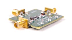


Critical to many new projects is a transparent interface to the board—one that you do not even notice is there. This connector-to-board interface is referred to as the board “launch,” where the RF energy transitions from the connector to the board. Figure 1 shows a typical design with 2.92-mm interface 40-GHz connectors on the edge of the board.

1. Shown is a 1:16 Wilkinson divider design that utilizes 2.92-mm connectors.
For designers moving to higher frequencies, i.e., into the 20-GHz range and higher, it will no longer suffice to just treat an SMA connector as a lumped 50-Ω element and mechanically join it to the printed-circuit board (PCB) using a standard footprint. For these designs, it’s now common to use 3D electromagnetic (EM) software tools, such as that supplied by COMSOL.
3D Tools Available to Designers
Designing a connector-to-board launch design is getting easier thanks to 3D EM software tools that have been available for years. Recently increased support from microwave connector suppliers is available as well.
Many microwave connector companies now provide 3D models of higher-frequency connectors that can be imported into 3D EM software tools. Some of these firms provide such models in a format that’s only compatible with a specific 3D EM software package. A fee may also be charged to receive the model. Signal Microwave models, on the other hand, are generic and can be used in any of the 3D EM software packages.