Passives Cram More Power into Ever-Smaller Packages

Download this article in PDF format.
Passive components, such as filters or attenuators, are often called upon to make critical changes to an RF/microwave filter in terms of amplitude or waveform shape. Modern system designers, however, are relentlessly faced with shrinking a system’s size, and usually without reducing the expected output power from that system. This means that passive components must get smaller while they provide increased power-handling capabilities.
In walking the exhibition floor at the recent IEEE International Microwave Symposium (IMS), trends in passive components were clear, with many suppliers extending their product lines to higher power levels and higher frequencies—many well into the millimeter-wave region—while pursuing ever-smaller packages to help system designers reach their goals for lighter weight and smaller size.
Passive components tend to be taken for granted at the systems-design level, because of their lack of active circuit elements, such as transistors, and need of a power supply. In many cases, a passive component, such as a coupler or power divider, can be added to a system whenever there’s enough space for them. Of course, this assumes that any passive component squeezed into a tight space can also dissipate whatever heat it generates by handling high signal power levels.
Directional couplers are one of the more common passive components added to a system after a certain design stage, usually to perform monitoring or testing purposes. Companies with broad product lines, such as Mini-Circuits, stock a variety of couplers for handling power levels as high as 250 W at frequencies from 5 kHz to 18 GHz. These couplers are available in core-and-wire and low-temperature-cofired-ceramic (LTCC) surface-mount designs as small as 0.12 × 0.06 in.

1. Following an industry trend in “smaller and higher-power” passive components, model SXPS-4-13-75+ four-way, 0° surface-mount power splitter/combiners are designed with higher impedance for use from 5 to 1300 MHz. (Courtesy of Mini-Circuits)
In addition to its many 50-Ω miniature surface-mount and coaxial components, Mini-Circuits also offers 75-Ω passive components for such applications as cable-television (CATV) systems. Components like the model SXPS-4-13-75+ four-way, 0° surface-mount power splitter/combiner are designed with the higher impedance for use from 5 to 1300 MHz (Fig. 1). The divider/combiner measures just 0.44 × 0.74 × 0.19 in. and comes in a shielded package with wraparound terminations to simplify soldering. Suitable also for DOCSIS systems, the component controls amplitude unbalance within 0.25 dB and phase unbalance within 1° across that wide frequency range. The typical full band insertion loss is 1.5 dB or less.
ARRA is well known for its passive components, in both coaxial and waveguide forms, built into rugged metal housings. While its components don’t necessarily follow the trend in miniaturization at higher frequencies, the firm offers a wide range of passive components that have been tested to perform with high reliability, including several types of fixed and variable attenuators, couplers, power dividers/combiners, and terminations for use at RF through millimeter-wave (mmWave) frequencies.
As an example, Form 0-3190 miniature stripline directional couplers use SMA female connectors to handle 50 W average power and 3 kW peak power across a frequency range of 500 MHz to 18 GHz. They maintain low insertion loss of only 0.5 dB across the full frequency band.
Moving Higher
Traditionally, passive RF/microwave components have been somewhat large, at least in package sizes large enough to support the use of coaxial connectors. As the push toward 5G wireless networks and commercial automotive radar systems encourages the use of passive components in the mmWave frequency range, many passive-component suppliers are higher-frequency components. Still, they are maintaining their coaxial connectors, albeit with smaller dimensions to accommodate the higher frequencies.
Krytar Inc., a long-time supplier of high-quality directional couplers and other passive components, has steadily climbed the frequency ladder with higher-frequency components, now well into the mmWave frequency range. The firm’s directional couplers are available in coaxial housings (Fig. 2) for a total frequency range of 300 MHz to 67 GHz with coupling values of 6, 10, 13, 16, 20, and 30 dB.
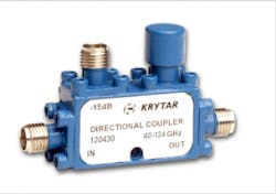
2. Many passive components, such as directional couplers, are supplied with coaxial connectors, such as this line of directional couplers with total frequency range of 300 MHz to 67 GHz with coupling values of 6, 10, 13, 16, 20, and 30 dB. (Courtesy of Krytar)
As an example, model 110067006 is an extremely broadband coupler with 6-dB coupling maintained within ±2.5 dB from 10 to 67 GHz. It also holds amplitude within ±0.75 dB from 10 to 50 GHz and within ±1.5 dB from 50 to 67 GHz. It uses 1.85-mm connectors to handle as much as 20 W CW input power with minimum directivity of 10 dB, maximum insertion loss of 4.4 dB, and maximum VSWR of 1.80:1. It measures just 1.30 × 0.50 × 0.62 in. and weighs a mere 1.3 oz.
Many users employ these precision couplers in test-and-measurement systems, where small size isn’t overly critical compared to a portable design application. Nonetheless, the size of the circuit boards and packaging is shrinking with the smaller wavelengths of mmWave frequencies, to the point where some packaging is barely large enough to support the screw mounting of high-frequency coaxial connectors, such as 2.4- and 2.9-mm connectors.
Such couplers find use in a wide range of commercial and military systems, including communications, electronic warfare (EW), and radar. In addition to its directional couplers, Krytar currently offers coaxial adapters and coaxial terminations operating through 67 GHz (essentially the company’s test characterization limit for the components).
Handling Power
In terms of minimizing rises in temperature as a result of high power levels, proper thermal design and management is essential to the essential tradeoff between possible power levels and miniaturization in passive RF/microwave components. This is in light of the fact that many manufacturers are faced with demands from system houses for more power in smaller packages. MECA Electronics has paid attention to the needs of the industry for high-power passive components while also meeting requirements for passive intermodulation distortion (PIM) at those high-power levels.
For example, MECA’s model LPT10-NM-MO1 termination/load is designed for use from 0.380 to 6.000 GHz and can be used for wireless-communications base station and in-building applications in 4G wireless networks (Fig. 3). With a robust metal housing and Type N male connectors, it achieves typical PIM performance of −170 dBc and low typical VSWR of 1.10:1. It’s one of many terminations that the company offers from stock.
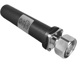
3. The model LPT10-NM-MO1 termination/load is designed for use from 0.380 to 6.000 GHz and can be used for wireless communications base stations and in-building applications in 4G wireless networks. (Courtesy of MECA Electronics)
As manufacturers of passive components attempt to keep pace with growing demands for mmWave products for 5G and automotive radar applications, some makers of passive components have been there for a while. One company, SAGE Millimeter, a long-time supplier of coaxial and waveguide passive components for microwave and mmWave applications, has routinely designed and manufactured such components as directional couplers, bandpass filters, and power dividers/combiners at mmWave frequencies.
As an example, the firm’s model SAT-FU-18819-S1 is a WR-19 waveguide orthomode transducer (OMT) that operates between 40 and 60 GHz (Fig. 4). The OMT separates a circular or elliptical polarized waveform into two linear, orthogonal waveforms or combines two linear polarized waveforms into one circular or elliptical polarized waveform.
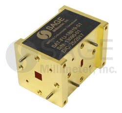
4. This WR-19 waveguide orthomode transducer (OMT) operates between 40 and 60 GHz. (Courtesy of SAGE Millimeter)
The OMT shows high port isolation (40 dB) and high cross-polarization cancellation while providing a low insertion loss. It uses 0.188- × 0.188-in. square waveguide for the antenna port and two WR-19 waveguide flanges for the horizontal and vertical ports. The OMT achieves 40-dB isolation and 35-dB cross polarization with the square waveguide antenna port.
With the company’s long time serving mmWave bands, it’s well-poised for the coming requirements in automotive and 5G applications and offers many of the components not always considered as part of a passive component lineup, such as antennas. Its model SAK-AL173223-42-C1 is a custom-built, K-band sector rectangular lens antenna for use from 17 to 22 GHz (Fig. 5). It delivers nominal half-power beam width of 31.5° vertically and 6.5° horizontally and 21.5 dBi nominal gain at a center frequency of 19.5 GHz. The sidelobe level is 15 dB or better from 17 to 22 GHz, and the typical return loss is 12 dB. The standard model is equipped with a WR-42 rectangular waveguide and a UG-595/U flange as its input port.
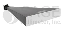
5. Many antennas, such as this custom built, K-band sector rectangular lens antenna for use from 17 to 22 GHz, are passive components that must be designed for appropriate power levels. (Courtesy of SAGE Millimeter)
These products represent just a very small sampling of the passive components currently available to support the trends in higher-power, smaller-sized, higher-frequency products. Such devices are also having an impact on the demand for 3D electromagnetic (EM) simulation software for use in optimizing the structures and configurations of passive circuits and components at higher frequencies. At one time considered something of a luxury in a designer’s tool chest, EM simulators are now being viewed as essential design partners for many engineers, to help them extract the optimum performance from a coaxial or waveguide section that’s operating with a signal wavelength just a fraction of its size.

About the Author
Jack Browne
Technical Contributor
Jack Browne, Technical Contributor, has worked in technical publishing for over 30 years. He managed the content and production of three technical journals while at the American Institute of Physics, including Medical Physics and the Journal of Vacuum Science & Technology. He has been a Publisher and Editor for Penton Media, started the firm’s Wireless Symposium & Exhibition trade show in 1993, and currently serves as Technical Contributor for that company's Microwaves & RF magazine. Browne, who holds a BS in Mathematics from City College of New York and BA degrees in English and Philosophy from Fordham University, is a member of the IEEE.
